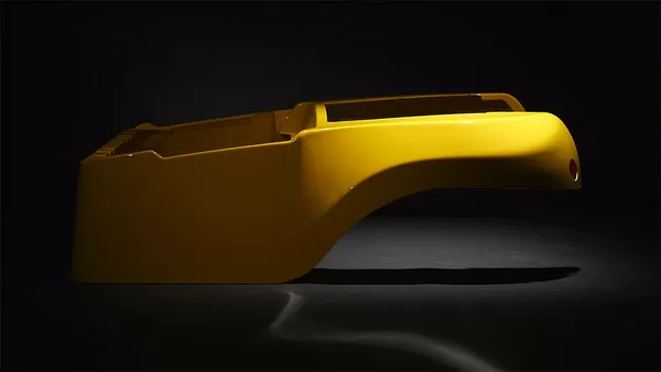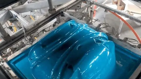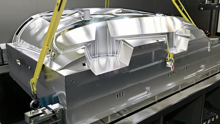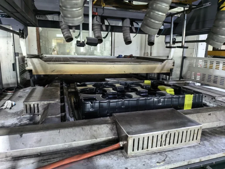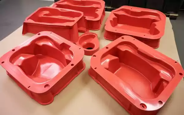
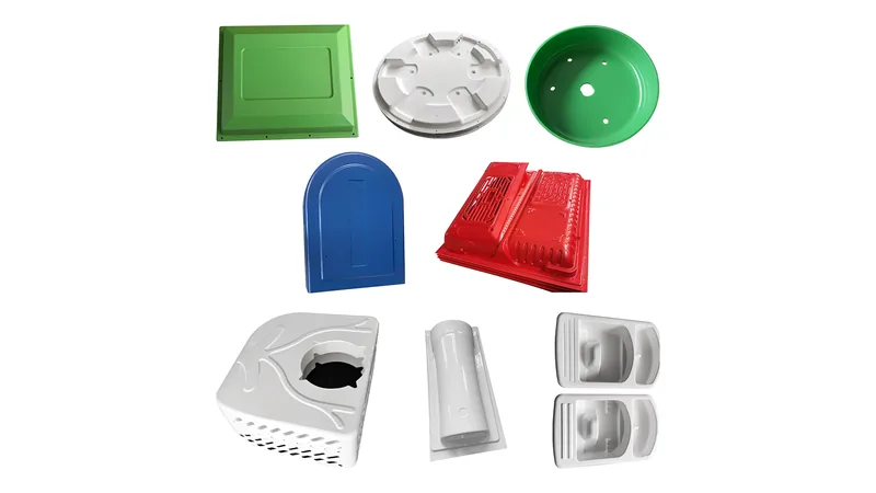
A thermoformed part never comes off the mold finished. It leaves the tool as a formed shell with clamping-frame scrap, oversize flanges and no usable holes, and it becomes a deliverable component only after CNC trimming and a chain of secondary operations. On heavy-gauge parts — machine housings, medical covers, industrial trays, structural panels — this post-forming stage defines the final geometry, the fit to mating hardware and a significant share of the piece price.
This guide explains how trimming actually works in heavy-gauge thermoforming, why 5-axis equipment has become the default, which tolerances are realistic, and what to confirm before approving a trimming and finishing plan. If you are new to the process itself, the vacuum forming overview covers forming fundamentals first.
- A formed part leaves the tool oversize; CNC trimming defines the final outline, holes and cut-outs.
- 5-axis trimming follows the formed surface, so cut-outs stay normal to curved walls and drafts.
- Fixturing and datum strategy, not spindle speed, drive trim repeatability across a production run.
- Set trim tolerances to forming and cutting capability, not to machined-metal expectations.
- Validate with first article inspection plus material tests where the application demands them.
- Plan secondary operations before tooling is cut, or assembly cost will surface late.
What Does CNC Trimming Remove From a Formed Part?
Trimming removes the clamping-frame scrap and oversize flanges left by the forming process and opens the holes, windows and cut-outs that the mold deliberately did not form. In short, it converts an oversize formed shell into a part that matches the drawing.
The formed sheet carries material you never see on the finished part: the peripheral frame that was clamped during forming, webs where the sheet draped into deep draws, and extra flange width left to absorb thickness variation. Several feature types are also better trimmed than formed. Holes on drafted or curved walls stretch out of round if formed, and holes in deep pockets are hard to vent and plug.
The usual engineering split is therefore: form what the mold can hold accurately, trim everything else. This division of labor is decided during DFM, ideally before the forming tool is cut, because it drives both mold cost and trim cycle time.
Why Is 5-Axis Trimming the Default for Heavy-Gauge Parts?
Because most heavy-gauge parts have curved walls, drafted flanges and cut-outs that meet the surface at angles, a 3-axis cutter forces awkward re-fixturing or leaves elliptical holes, while a 5-axis head follows the formed geometry in a single setup.
That single setup matters more than raw machine speed. Every re-clamp adds a datum transfer, and every datum transfer is a chance for hole-to-edge relationships to drift. On parts approaching the 2,500 mm forming-length range, handling itself introduces variation, so fewer clamps is a tolerance strategy, not just a productivity choice.
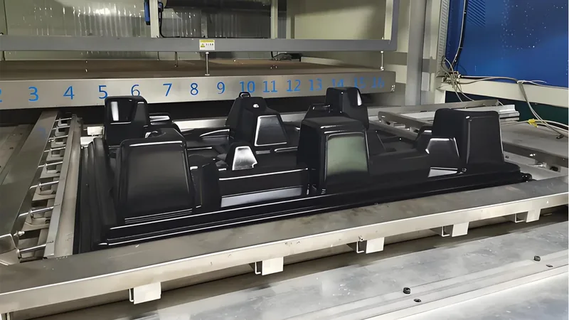
In our plant, every formed part is trimmed on a 5-axis CNC centre, and the trimmed outline follows the forming tool directly.
Every part we trim runs on 5-axis CNC equipment, with the trimmed outline following the forming tool. For your project that means the formed surface itself becomes the locating datum, which simplifies fixture design and keeps hole-to-edge relationships consistent across the run.
For a designer, the practical consequence is that holes should be drawn normal to the formed surface, and any feature that must stay truly round and vertical should sit in a near-flat region or be designed as a post-formed, trimmed feature. State these intentions on the drawing; a trimming programmer cannot infer them from a 3D model alone.
"A cleanly cut edge means the part is dimensionally correct."False
A polished edge tells you the cutting parameters were right, not that the part matches the drawing. Trim accuracy depends on fixturing and datum transfer, so a part can look excellent and still miss hole positions by a millimetre.
"Edge quality and dimensional accuracy must be verified separately."True
Treat visual edge finish and dimensional inspection as two distinct checks with separate acceptance criteria. Reviewing them together at first article prevents a good-looking part from passing on appearance while failing hole or outline geometry.
How Do You Keep Trim Tolerances Tight?
Tight trim tolerances come from controlling the input: repeatable formed parts, fixtures that locate on the formed surface, and compensation for post-form shrinkage. The cutting step itself is usually the most repeatable link in the chain.
Three inputs dominate. First, sheet thickness variation: heavy-gauge sheet is processed in the 0.5–15 mm range, and thinner zones created during deep draws change local stiffness and springback at the trim edge. Second, material shrinkage: ABS, PC and olefin sheets contract differently after forming, and parts trimmed warm will move again as they cool. Third, fixturing: cast or machined nests that reproduce the formed surface hold the sheet the way the mold did, so the cutter sees the same geometry every cycle. Equalizing the part to a stable temperature before trimming is standard practice on tight-tolerance work.
The table below gives conventional ranges for heavy-gauge work; actual values depend on material, part size and equipment, so treat them as planning figures rather than guaranteed specs.
| Feature on a trimmed part | Conventional range | Main driver |
|---|---|---|
| Trimmed edge to formed surface | ±0.5 – ±1.0 mm | Forming shrinkage and sheet variation |
| Hole or slot position | ±0.5 mm | Fixture datum on the formed surface |
| Hole diameter, CNC cut | ±0.5 mm or tighter, as agreed | Cutter wear and local melt behavior |
| Flat flange flatness | 0.5 – 1.0 mm over part length | Residual stress and cooling history |
| Overall length up to about 2,500 mm | ±1.0 mm or wider at full size | Material shrinkage at scale |
"If the first trimmed sample fits the assembly, the whole run will fit too."False
One sample proves the program and fixture concept, not process stability. Forming drift, cutter wear and fixture wear all appear over a batch, so a sample that fits today says little about part 500.
"Trim consistency must be proven across a batch, not on one part."True
A sensible approval samples parts across the run and checks hole positions and outline against the datum scheme. This catches forming drift early, while it is still a parameter adjustment rather than a containment action.
Which Secondary Operations Complete a Thermoformed Part?
Beyond trimming, the most common secondary operations are CNC drilling and routing of extra features, hardware insertion, bonding of sub-components, gasket application, edge finishing and painting or texturing.
Each has an engineering catch. Hardware: heat-staked or press-fit inserts give far better pull-out strength than self-tapping screws in a 2–4 mm formed wall. Bonding: ABS, PC and PC/ABS accept adhesives readily, while PP and HDPE need surface treatment before anything sticks.
Sealing and appearance have their own rules. When a formed enclosure must meet a rated protection level, gasket selection and flange flatness decide the result as much as the gasket groove does — the rating language itself comes from IEC 60529, the standard that defines the degrees of protection provided by enclosures, which buyers typically invoke for IP-rated formed covers. Clear PMMA covers are flame-polished at the trim line so the finished edge matches the clarity of the formed surface; ISO 13468 specifies the total luminous transmittance test used to confirm that a transparent part still delivers its specified light transmission after forming and finishing.
The material library here covers PVC, ABS, HDPE, LDPE, PP, PC, PMMA, PA6/PA66, POM, TPE, TPU, TPV and alloys such as PC/ABS, ASA and PP/GF. That breadth matters at the finishing stage because each family responds differently to bonding, staking and painting — a finishing plan validated on ABS will not transfer to PP without surface treatment.
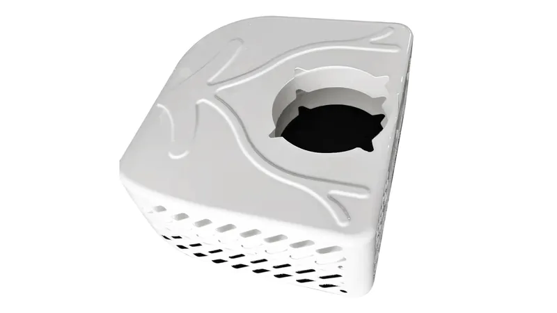
Assembly-ready delivery is the usual goal: trimmed, drilled, hardware-inserted and inspected parts that drop into the customer line without further handling. The heavy-gauge application overview shows how finished parts map to equipment, automotive, medical and logistics use cases.
How Do You Validate Trimmed and Finished Parts?
Validation combines dimensional verification with material and functional checks. Dimensionally, the first production part receives a full first article inspection1 against the drawing, as described in our guide to first article inspection for heavy-gauge thermoformed parts, and the results then translate into simple in-process gauges for the run.
Material-wise, forming and trimming together must not degrade the sheet beyond agreed limits. ASTM D638 specifies the tensile test used to validate both the incoming thermoformable sheet and samples cut from finished parts, so the tensile values agreed on the drawing effectively define how much the forming cycle and trim handling are allowed to change the material.
For housings and covers that sit near heat sources, heat resistance is checked in the same spirit: HDT2 values per ASTM D648 or ISO 75-2 tell you where a formed panel starts to deflect under flexural load. Industry references such as the SPE Thermoforming Division collect process guidance that many shops use to align trim and inspection practice.
What Should You Confirm Before Approving a Trimming Plan?
Before signing off, confirm the tolerance scheme against the drawing datums, the fixture concept, the full hole and cut-out list, and exactly what the quote includes in trimming, finishing and inspection.
On files: bring both the 3D model and a 2D drawing with GD&T3 datum structure. The model carries geometry; the drawing carries which features are critical and how they are measured. On scope: ask whether fixture amortization, edge finishing, hardware and inspection are quoted separately, because these line items quietly move piece price between suppliers.
On volume: a plant that supports prototyping, small batch and large batch production can keep the same fixture philosophy from pilot to full run, which protects your validation work. The DFM checklist for heavy-gauge thermoformed parts and molds is a useful gate before tooling release.
"You can get a firm trimming quote from a 3D model alone."False
A model shows geometry but not which tolerances are critical, where datums sit or how many holes need gauging. Without the 2D drawing, any supplier is guessing at inspection effort, and the number you receive will move once the drawing arrives.
"Firm quotes need the model plus a 2D drawing with datums and hole data."True
With both documents, the supplier can price cutting time, fixture effort and inspection realistically and commit to the numbers. It also gives you an apples-to-apples basis when comparing quotes between suppliers.
Beyond documents, agree on the rework path before it is needed: which edge defects are touched up in-house, who inspects after rework, and how a deviation is documented. Ten minutes on this topic prevents most post-approval friction.
Forming and finishing run on 20+ vacuum forming and thermoforming machines across 45+ production lines in total, at a reference monthly capacity of about 100,000–200,000 pieces. The practical meaning for a buyer: post-forming capacity is planned alongside forming, so a large batch does not stall in a trimming bottleneck.
FAQ
Can a thermoformed part hold tolerances as tight as a machined part?
No, and it should not try. Formed parts carry material-level variation from the sheet and the forming cycle, so trim tolerances are set to what forming and cutting jointly deliver, typically within the ranges shown above. Requiring machined-metal bands on a formed part inflates cost without adding function.
Should holes be formed in the mold or trimmed afterwards?
Alignment-critical holes and any hole on a drafted or curved wall should be trimmed, because forming stretches and distorts them. Holes in near-flat, well-vented regions can be formed when volume justifies the tooling detail. Decide this during DFM, not after the mold is cut.
What files do you need to quote trimming and finishing?
A 3D CAD model plus a 2D drawing with datum structure, critical dimensions, material specification and volume split. Add mating-part data when hardware or gaskets are involved. With that package, a supplier can commit to cycle time, fixture cost and inspection scope in one pass.
How much of the formed sheet is trimmed away?
It depends on the part, but expect the clamping frame, perimeter flange and web areas to account for a meaningful share of the sheet, often more on deep-draw parts. That scrap is priced into the part from the start, which is why sheet utilization is a forming-design topic, not just a trimming one.
Can secondary operations be done by the same supplier?
Yes, and it is usually the lower-risk route: when trimming, staking, bonding, gasketing and final inspection happen in one plant, datum accountability stays with one partner. The ZetarVac service scope covers formed parts through assembly-ready delivery, which shortens the loop when a fit issue needs a corrective cut.
If you are evaluating suppliers at the procurement stage, the most useful next step is a drawing review: send your drawings through the ZetarVac vacuum forming manufacturer page and an engineer will assess trim strategy, tolerances and finishing scope against your application.
-
FAI: First Article Inspection, a full dimensional and functional verification of the first production part against the drawing before a run is released. ↩
-
HDT: Heat Deflection Temperature, measured per ASTM D648 or ISO 75-2, the temperature at which a standard bar deflects a defined amount under flexural load. ↩
-
GD&T: Geometric Dimensioning and Tolerancing, a standardized system for defining tolerances and datums on engineering drawings. ↩