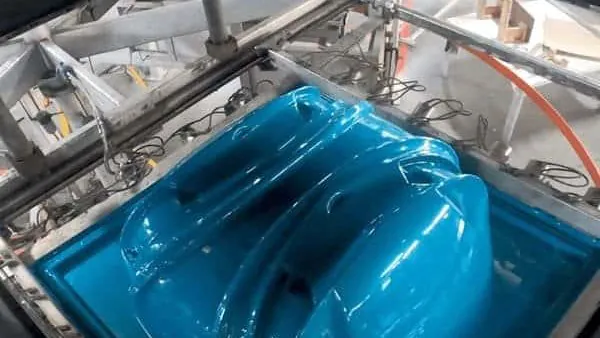
Heavy-gauge thermoforming looks deceptively simple: heat a plastic sheet, stretch it over a single-sided tool, apply vacuum, cool, trim. The problems that surface in production are not simple. On a vacuum forming line running 0.5–15 mm sheet, most defects trace back to three variables — sheet temperature distribution, vacuum path design and cooling strategy — and each interacts with the material grade and the part geometry. This article walks through the production problems that buyers and process engineers meet most often on formed housings, enclosures, trays and structural covers, explains the mechanism behind each defect, and lists the checks that separate a stable forming process from one that drifts between shifts.
- Uneven wall thickness is a sheet temperature and draw ratio problem before it is a vacuum problem; correct heater zoning and plug geometry first.
- Webbing, bridging and washed-out detail come from excess sheet area, tool design and leaks in the vacuum path — not from weak material.
- A passing first article does not prove stability. Sheet moisture, regrind content, heater ageing and ambient conditions move the process window every week.
- Tolerance capability is set by material shrinkage and tool design; tight trimmed features should come from 5-axis CNC trimming, not from the forming step.
- Formed enclosures for electrical equipment need flammability and ingress protection validation (UL 94, IEC 60529 or NEMA 250) early in design, not after tooling is cut.
- Most production disputes disappear when sheet temperature, cycle time and cooling are documented per material lot and per machine.
Why Do Thermoformed Parts Come Out With Uneven Wall Thickness?
Wall thickness variation is primarily a sheet temperature problem, not a vacuum problem. If the sheet is hotter in the centre than at the clamped edges, or hotter on one face than the other, the hot zones stretch first and thin out while cooler zones barely move. Correct heater zoning and top-to-bottom heat balance before touching vacuum settings or plug geometry.
The draw ratio1 tells you where the thinning will land before the first sheet is heated. Material that travels to the bottom of a deep cavity is drawn thinnest, while the flange keeps close to its original gauge. On male tools the corners thin first; on female tools it is the bottom corners. A drawing that asks for a thick floor from a thinner sheet has to budget for that local thinning, not just the average.
Material choice sets how much temperature error the process can absorb. ABS has one of the widest forming windows in common use and forgives uneven heater zones; PC needs more uniform heat; PP sags heavily mid-window and demands sag control. The useful shop-floor check is the same for any grade: probe or IR-scan the sheet as it leaves the heater and compare the readings against the forming window the material supplier recommends.
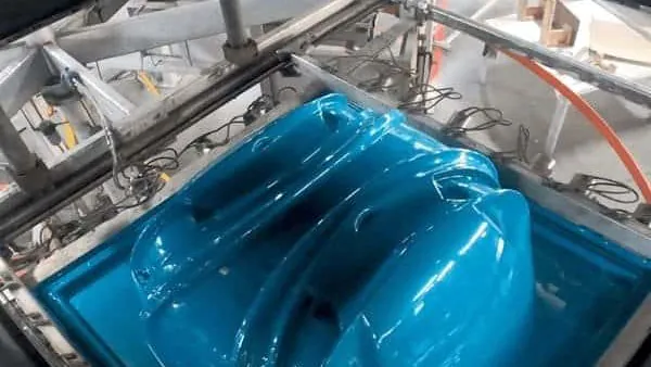
On deep draws, vacuum alone cannot pull material to the bottom while it is still hot enough to stretch. A plug assist pre-stretches the sheet toward the cavity so the floor forms at forming temperature, and zoned heaters bias heat toward the areas that must draw deepest. Both belong in the tooling conversation before quotes are issued, because they change tool cost and cycle time together.
"A bigger vacuum pump is what fixes thin corners on deep draws."False
More vacuum only speeds evacuation; it cannot keep the sheet hot enough to stretch on the way down. Without plug assist and heater zoning, a stronger pump simply pulls the flange down faster and leaves the corners just as thin.
"Deep draws need plug assist and heater zoning, not vacuum capacity alone."True
Pre-stretching with a plug keeps the bottom wall at forming temperature while it is drawn, which is where thickness is actually won or lost. Zoned heaters concentrate heat where the draw is deepest, and both measures are decided in tooling design rather than patched in after the tool exists.
Once zoning and plug geometry are right, the remaining thinning is predictable. It should appear as an explicit wall thickness callout on the drawing, agreed with the moulder at design review, instead of being discovered on the first article.
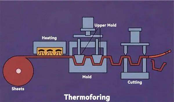
Webbing, Bridging and Vacuum Loss: Forming Defects With Mechanical Causes
Webbing is the fold of excess material that bridges between two tall features on the tool. It comes from too much sheet area for the geometry, features spaced too closely, or a sheet that has sagged too far before forming. The fixes are mechanical: trim the frame size where the design allows, re-space features, add vacuum holes between the features, or move faster from heater to tool so the sheet is not over-sagged.
Slow, inconsistent formation with weak detail usually points at the vacuum path rather than the sheet. Gaskets harden and leak, plenum passages clog, and vacuum holes block with mold release residue or debris. The shop-floor test is a vacuum decay check on the sealed tool: pull vacuum, close the valve and watch how fast the reading falls. A tool that cannot hold vacuum cannot form detail, no matter what the heater does.
Blisters and surface streaks have a different origin: moisture. Hygroscopic2 materials such as PC, ABS and TPU absorb water from the air, and that moisture flashes to steam inside the heater, leaving bubbles, silver streaks or a foamed surface. Drying sheet before forming and controlling storage humidity are inexpensive habits that eliminate an entire defect class before it reaches the tool.
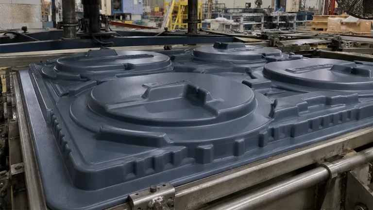
The plant forms 0.5–15 mm sheet on more than 20 vacuum forming machines, with a maximum forming length of about 2,500 mm. At that scale a cold edge zone on the heater shows up immediately as a thick, under-formed flange on a large panel, which is why heater mapping matters more as the part gets bigger.
Why Does the First Article Pass but Production Parts Keep Drifting?
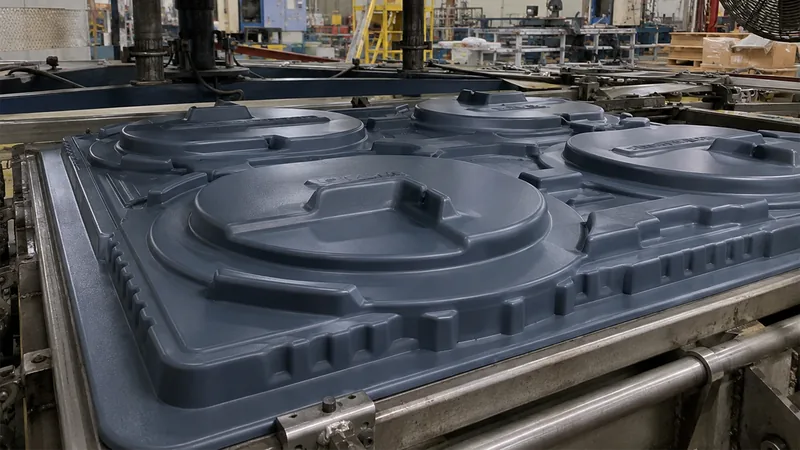
Because the first article is made on a fresh setup with full operator attention, while production runs on saved heater settings and different material lots. Sheet moisture, regrind content, heater ageing and ambient temperature all move the process window. Stability comes from documented settings and incoming material control, not from the first-off report.
Heaters age. Element output drops, reflectors foul, and a zone that reached its setpoint last quarter may no longer reach it on the same timer setting. If nothing is measured, the compensation happens silently: an operator stretches heating time, the sheet over-sags, and webbing appears on a tool that ran clean for months. A periodic zone-by-zone temperature check against the recorded baseline catches this before scrap does.
Material lots drift too. A new batch can arrive wetter than the last, a regrind percentage can change, and each shift moves the heating and drying behaviour of the sheet. The control is procedural: record drying time and temperature per lot, note the regrind ratio, and run the first sheet of every new lot against the documented settings before releasing the machine to full rate.
When one tool runs across several machines, machine-to-machine differences add a third layer of variation. The practical answer is a setup sheet that specifies top and bottom heater zone temperatures, heating time, vacuum hold and cool time per machine, plus a first article inspection3 whenever the tool moves. That paperwork is what makes a passing result repeatable rather than lucky.
"A signed-off first article proves the process is stable for production."False
A first article verifies the tool and the setup at one moment in time, with one operator and one material lot. It says nothing about how the process behaves when the heater ages or the next lot arrives, which is exactly where production drift starts.
"Process stability comes from documented settings and lot control, not from the first article."True
The settings sheet, drying records and periodic heater checks are what hold the process inside its window over weeks of running. The first article remains a tool acceptance step, while stability is demonstrated by measurement repeated across lots and shifts.
What Tolerances Can a Heavy-Gauge Vacuum Forming Process Hold?
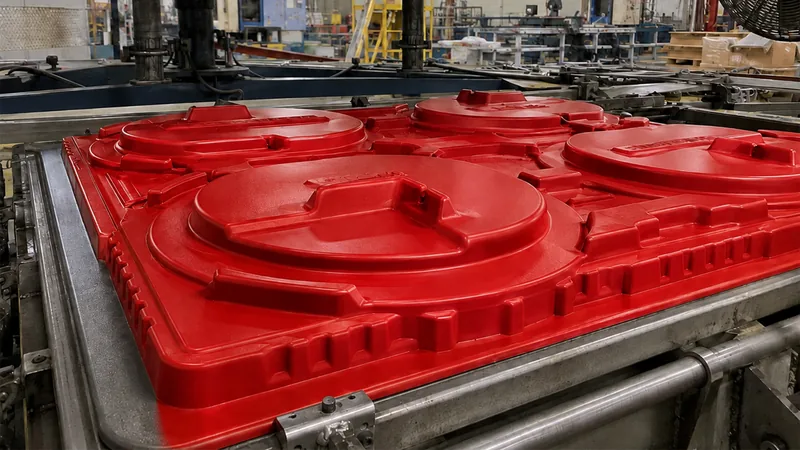
Realistic tolerances depend on material shrinkage, part geometry and tool design rather than on the forming machine alone. Well-controlled grades such as ABS or PC/ABS hold close, repeatable dimensions on small trimmed features, while large panels and deep draws move noticeably more because the free surface shrinks without restraint. Anything tighter than the forming step can deliver should be produced by CNC trimming, not by asking the sheet to hold it.
| Feature | What governs the capability | How to tighten it |
|---|---|---|
| Trimmed outline on large panels | Shrinkage of the unrestrained surface during cooling | 5-axis CNC trimming against the forming tool datum |
| Hole and slot positions | Trim method and fixture accuracy | CNC drill or trim in a fixture, not in the mold |
| Wall thickness | Draw ratio, heater zoning and plug geometry | Zoned heaters, plug design, draw ratio review at design stage |
| Flatness of wide panels | Cooling uniformity and part geometry | Controlled cooling, hold fixtures, annealing where the grade allows |
Mold shrinkage4 is the reason forming-only tolerances cannot simply be tightened on request. A sheet cools from forming temperature against a single-sided tool, so the free surface shrinks without restraint, and the amount depends on the grade, the direction of stretch and the local wall thickness. Male and female tools distribute that shrinkage differently, which is why the same drawing can hold differently on two tools.
"Tighter tolerances just mean slightly more tooling cost."False
The limiting factor is not the tool but the material: shrinkage variation and post-forming movement set a floor on what forming alone can hold. Chasing forming-only tolerances below that floor produces scrap and disputes, because no amount of tool polish changes how much a cooling panel moves.
"Tight trimmed features should be produced by CNC trimming, not by forming."True
Forming sets the general geometry; trimming against the forming tool datum sets the accuracy of outlines, holes and slots. Separating the two steps lets the drawing call tight tolerances where they matter and generous ones where the sheet physics decides.
The practical consequence is a division of labour: the tool owns the shape, the trimming centre owns the precision. That separation is built in here, because formed parts are finished on a 5-axis CNC trimming centre whose cut follows the forming tool as its reference.
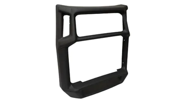
Formed parts at this plant are trimmed on a 5-axis CNC trimming centre, with the trimmed outline following the forming tool as its datum. That is why hole patterns and cut-outs on housings and trays can be held to machining accuracy even when the formed body itself is governed by shrinkage.
Which Standards Should a Formed Enclosure or Tray Be Checked Against?
Flammability comes first for anything that houses electronics or motors. UL 94 classifies the flammability of plastic materials, and a formed enclosure destined for electrical equipment is normally assigned a required rating — such as HB, V-0 or 5VA depending on the application — during the product safety review, which constrains the material grade chosen before tooling is cut. UL 746C extends this picture for polymeric materials used inside electrical equipment.
Heat resistance is the second gate. ISO 75-2 specifies how the heat deflection temperature of a plastic is measured under a defined flexural load5, which tells you how far above room temperature a formed housing can carry load before it starts to relax. For clear covers, ISO 306 Vicat softening point gives a complementary indication of where the part begins to sag under its own weight.
Mechanical validation uses the same methods as the rest of the plastics industry: ISO 527-2 defines the tensile test run on thermoformed sheet, and it is the standard way to confirm that a sheet lot actually delivers the strength the design assumed. For protective covers and guards, puncture resistance measured per ISO 6603-2 adds an instrumented impact check that bend tests cannot provide.
Ingress protection is decided by the enclosure standard, not by the plastic. IEC 60529 defines the IP code for enclosures, and NEMA 250 defines Type ratings such as Type 4 and 4X for formed electrical enclosures; a formed cover meets them through gasket design, flange geometry and fastening, which is why the moulder should see these requirements at quotation stage.
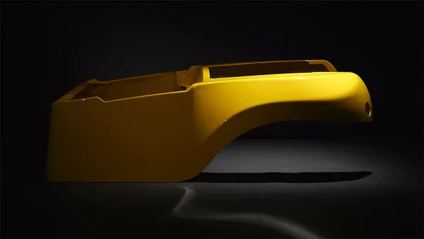
Material selection closes the loop: ABS and PC/ABS for equipment housings and automotive interiors, ASA for outdoor housings, PC for clear guards, PMMA for high-clarity display covers, HDPE and PP for trays and liners, and PP/GF where stiffness must go up. The SPE Thermoforming Division publishes process guidance worth reading alongside any material datasheet.
The grade list here covers PVC, ABS, HDPE, LDPE, PP, PC, PMMA, PA6, PA66, POM, TPE, TPU, TPV, PC/ABS, ASA and PP/GF, each mapped to applications such as equipment housings, automotive interiors, clear guards, industrial trays and structural parts. Naming the grade early means the forming window and the standards list can be checked together, before tooling is quoted.
FAQ
Why are the corners of my thermoformed part thin and weak?
Corners thin where the draw ratio is highest. Raise heater zone output over the areas that must stretch most, check the plug geometry and its temperature on deep draws, and review whether the corner radius on the tool can be increased. A small radius change often recovers more wall than any process adjustment.
How does sheet thickness affect cycle time?
Heat has to soak through the full gauge, so heating time grows roughly in proportion to sheet thickness, and cooling time grows with it. Doubling the gauge does not merely add a few seconds; it re-plans the cycle, the sag behaviour and the clamping, which is why gauge should be fixed before tool design is finalised.
Can warped heavy-gauge parts be corrected after forming?
Partly. Cooling under a hold fixture, controlled racking and — for some grades — annealing can pull a part back toward shape, but corrections are never as stable as getting the cooling right in the first place. Treat post-correction as a containment step while the cooling strategy is fixed upstream.
How do I tell whether a defect is a material problem or a process problem?
Change one variable at a time against a documented baseline: form a sheet from a known-good lot at the recorded settings. If the defect follows the sheet, look at the material lot and its drying history; if it stays, the process or tool has drifted, and the heater check is the first place to look.
Where can I review the full forming sequence step by step?
ZetarVac publishes a step-by-step breakdown of the heavy-gauge thermoforming process and an overview of the thermoforming production process covering heating, forming, cooling and trimming in sequence.
If you want to keep exploring before you compare suppliers, read the ZetarVac vacuum forming guide for forming methods, materials and tooling options in one place, or see how a heavy-gauge vacuum forming project is handled from sheet selection to final trimming.
-
Draw ratio: The ratio between the surface area of the formed part and the area of sheet clamped in the frame; higher draw ratios mean more stretching and more thinning. ↩
-
Hygroscopic: Describes plastics such as PC, ABS and TPU that absorb moisture from the air; trapped moisture turns to steam during heating and causes blisters and streaks. ↩
-
First article inspection: Full dimensional and functional verification of the first part off a new tool or setup, used to accept the tool rather than to prove ongoing process stability. ↩
-
Mold shrinkage: The percentage dimensional change of a plastic as it cools from forming temperature to room temperature; it varies by grade, direction of stretch and local wall thickness. ↩
-
HDT: Heat deflection temperature, the temperature at which a standard bar deflects a specified amount under flexural load, measured per ISO 75-2 or ASTM D648. ↩