Thermoforming converts a flat thermoplastic sheet into a large, functional part through four controlled stages: heating, vacuum forming, cooling and trimming. It is the manufacturing route behind heavy-gauge plastic components — equipment housings, machine covers, trays, liners and structural parts — because it scales from one-off prototypes to monthly production volumes without locking the project into disproportionate tooling cost. This guide walks through the complete production process: what happens at each stage of the cycle, the process windows that decide part quality, how to select sheet material, and the failure modes a buyer should be able to name when reviewing formed parts or supplier quotations.
- Heavy-gauge thermoforming works with cut sheet from 0.5 to 15 mm thick and produces structural parts such as equipment housings, covers, trays and liners.
- The production cycle has four stages: sheet heating, vacuum forming against the tool, controlled cooling and 5-axis CNC trimming.
- Wall distribution — not the starting sheet gauge alone — decides the stiffness and impact behaviour of the finished part.
- Material selection between ABS, HDPE, PP, PC and PMMA is driven by heat deflection, clarity, weatherability and flammability requirements.
- Warp, blisters and thin corners are process-window failures, and each has a specific, checkable cause.
- A documented process window with realistic tolerances predicts production stability better than a single passing first article.
What Is the Thermoforming Production Process?
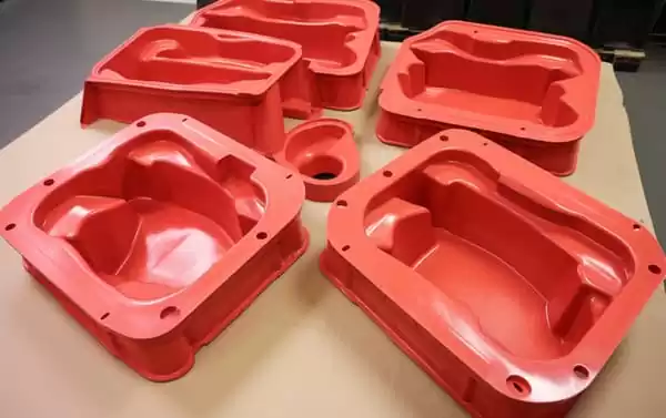
The thermoforming production process heats a thermoplastic sheet until it reaches a pliable forming temperature, stretches it against a mould using vacuum, cools it until it holds its shape, then trims the flashed outline to finished dimensions. In heavy-gauge work the starting sheet runs from 0.5 to 15 mm, and the output is structural: equipment housings, machine guards, trays and load-bearing components.
The heavy-gauge branch differs from thin-gauge packaging work in three practical ways. Sheet is cut to size rather than roll-fed, parts are measured in hundreds of millimetres rather than centimetres, and the formed shell usually carries loads or protects equipment, so wall distribution and stiffness matter as much as appearance. Vacuum forming is the most common variant, where atmospheric pressure presses the sheet onto a single tool; pressure forming adds air pressure on the opposite side when surface detail and texture definition justify the extra tooling cost.

How Does a Heavy-Gauge Thermoforming Cycle Work?
A heavy-gauge cycle runs in four stages: clamp and heat the cut sheet, form it over the tool under vacuum, cool it below its heat deflection temperature, then trim the part on a multi-axis CNC. A 3–6 mm part typically cycles in a few minutes to about ten minutes, depending on gauge, material and draw depth.
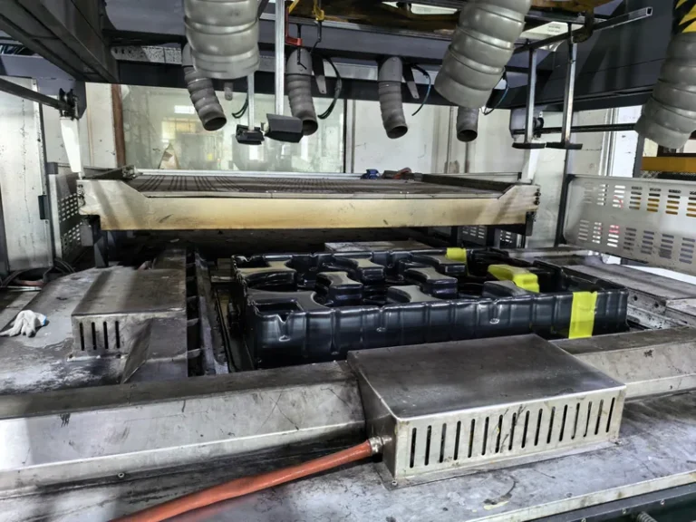
Step 1 — Sheet heating: The sheet is clamped in frames and moved into an infrared oven. Thick sheet is heated from both sides, and heater zones are set independently so the centre and edges reach forming temperature together — the single biggest lever on wall distribution. Operators judge readiness by sag: the sheet droops under gravity as it softens. For each material the target sits below the Vicat softening point1, the temperature where the surface begins to slump, so the sheet stretches without tearing or sticking to the tool. Dark pigmented sheet absorbs infrared faster than natural sheet and reaches forming temperature sooner.
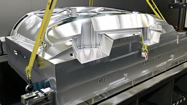
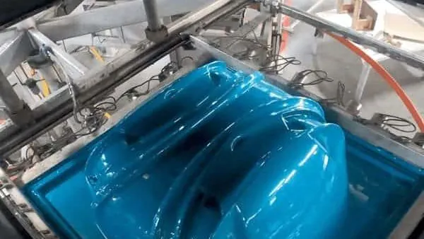
Step 2 — Forming under vacuum: The hot sheet is shuttled over the mould and sealed against the platen. Vacuum is drawn, and atmospheric pressure — roughly 0.09 to 0.095 MPa of effective pressure differential once the cavity is evacuated — presses the sheet onto the tool surface. Vent holes in the tool let trapped air escape from deep pockets. For deep draws, a plug assist pushes the sheet into the cavity first so material distributes before the vacuum pulls it tight against the mould walls, and a deliberate pre-stretch bubble keeps corners from thinning out.
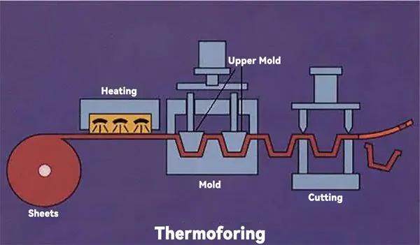
Step 3 — Cooling: The part must cool below its heat deflection temperature2 — the load-bearing temperature defined in tests such as ISO 75-2 — before it is released, or it will distort as it leaves the tool. Fans, mould cooling channels and cooling plates remove the heat; on thick gauge sheet, cooling is usually the longest stage of the cycle. The key detail is symmetry: if one face cools faster than the other, the part bows toward the cold side.
Step 4 — Trimming and finishing: The formed shell carries excess material, or flash, that is removed on a CNC trimming centre. On a 5-axis machine the cutting head follows the forming tool geometry, so the trimmed outline repeats consistently across the batch. Slots, mounting holes and cut-outs are machined in the same setup where the fixture allows.
ZetarVac runs more than 20 vacuum forming and thermoforming machines processing sheet from 0.5 to 15 mm, with a maximum forming length of about 2,500 mm. For buyers this means large equipment housings and covers can be formed as a single shell instead of being assembled from several smaller panels.
Which Materials Suit Heavy-Gauge Vacuum Forming?
The workhorse materials are ABS, HDPE, PP, PC and PMMA: ABS for equipment housings and automotive interior parts, HDPE for industrial trays and equipment liners, PP for trays and boxes, PC for clear guards and protection covers, and PMMA for high-clarity display parts. Selection is driven by heat deflection, impact behaviour, clarity, weatherability and any flammability requirement.
Material properties are verified on the sheet before forming: ISO 527-2 defines the standard tensile test method used to confirm that a thermoformed sheet retains the strength of the parent resin after heating and stretching3. For enclosures that protect electrical equipment, UL 94 governs flammability classification and is the rating many buyers require before a formed housing can be approved4.
| Material | Typical formed parts | Property that drives the choice |
|---|---|---|
| ABS | Equipment housings, cases, guards, automotive interior parts | Balanced impact strength, cost and paintability |
| HDPE | Industrial trays, equipment liners, storage boxes | Chemical and moisture resistance, toughness |
| PP | Automotive interior parts, trays, packaging, boxes, equipment liners | Heat resistance and fatigue performance |
| PC | Clear guards, equipment protection covers, automotive parts | High impact strength with optical clarity |
| PMMA | Clear covers, luminaires, display and retail parts | Total luminous transmittance and surface finish |
| PC/ABS | Automotive interiors, equipment housings, guards | Heat and impact balance of both resins |
| ASA | Outdoor equipment housings, automotive exterior parts | UV and weather resistance without paint |
| TPE / TPV | Soft liners, seals, soft automotive and industrial parts | Flexibility and durometer selection |
Two selection notes are worth remembering. PC/ABS and ASA exist because a single resin rarely satisfies every requirement on outdoor or automotive housings — blends and weatherable grades trade some cost for UV stability. And clarity grades down as gauge rises: a thick PMMA cover transmits less light and carries more internal stress than a thin one, so clear parts deserve early prototype review rather than late-stage optical correction.
What Tolerances and Wall-Thickness Rules Apply?
Formed walls are always thinner than the starting sheet wherever the sheet stretches: expect roughly 10–25% thinning on moderate draws and more at deep corners. Formed-part tolerances are wider than machined plastics — commonly around ±0.5 mm on small features, with progressively wider allowances on large outlines as part size, gauge and draw depth grow — and the trimmed outline follows the forming tool.
Geometry rules keep the process predictable. Draft angles of roughly 2–5° help the part release and reduce corner thinning; inside radii should be at least equal to sheet thickness; and the draw ratio — part depth relative to its smallest opening — should stay near 1:1 for plain vacuum forming, with plug assist or pressure forming handling deeper geometries. Trim allowance must be designed in from the start, because the flash ring is clamped during forming and cannot be skipped.
"Once the first article passes inspection, the production run will stay within tolerance."False
A first article is produced under carefully tuned conditions, but bulk production shifts with heater aging, ambient temperature and incoming sheet batches. Without a documented process window, a passing first article only proves the tool can work, not that the process will hold across a full run.
"Production stability comes from a documented process window, not from a single good part."True
A qualified window pins heater zone settings, sheet temperature, mould temperature and cooling time, so shift-to-shift variation lands inside an already-proven band. That is what turns a good first article into a repeatable monthly output.
Tooling quality drives geometric repeatability as much as the cycle does. Vent hole placement, plug geometry and surface finish all leave their mark on every part the tool produces, which is why formed moulds are CNC machined directly from the part model rather than approximated by hand.
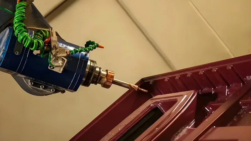
Formed parts at ZetarVac are trimmed on a 5-axis CNC trimming centre whose cutting path follows the forming tool, so the outline stays consistent across the batch. The plant supports prototyping, small batch and large batch production, so the same trimmed definition carries from first samples into series volume.
Why Do Formed Parts Warp, Blister or Show Thin Corners?
All three defects trace back to the process window rather than bad luck: warp comes from uneven cooling and locked-in stresses, blisters from overheated or wet sheet, and thin corners from a draw ratio the material cannot follow. Naming the cause is most of the fix.
Warp and bow: When one face of the part cools faster than the other, differential shrinkage pulls the panel toward the cold side. The fix is symmetric cooling — balanced fans and mould temperature held in the material’s recommended range — plus adequate cooling time before release, especially on large flat panels.
Blisters: Bubbles form when moisture in hygroscopic sheet such as ABS or PC expands during heating, or when a heater zone overpowers the sheet and starts degradation. Dry the sheet before forming and verify heater zone settings against the observed sag profile instead of simply pushing temperatures up.
Thin corners and webs: Corners thin out when the draw ratio exceeds what plain vacuum can distribute, and webs bridge between tall, closely spaced features when the sheet folds instead of stretching. Deeper draft, larger radii, plug assist, pre-stretch or changed feature spacing solve most cases. The full failure catalogue with remedies is covered in the site guide to common thermoforming problems.
"Thicker sheet always produces a stronger formed part."False
Strength follows the wall distribution the process leaves behind, not the incoming gauge. A well-formed 4 mm part with controlled corner thickness can outperform a poorly formed 6 mm part whose corners have thinned dramatically — and the thicker sheet slows heating and cooling for no gain.
"Wall distribution, not sheet gauge alone, decides part performance."True
What matters is how much material survives at the corners and load paths after forming. Reviewing the thickness map of a formed sample tells you more about part strength than the sheet specification does.
FAQ
How thick can the sheet be in heavy-gauge thermoforming?
Heavy-gauge work commonly covers sheet from about 0.5 to 15 mm. ZetarVac processes the full 0.5–15 mm range, with a maximum forming length of about 2,500 mm, so thick structural shells and large covers can be formed in one piece. The practical ceiling for a given part depends on material, heater power and draw depth.
Is pressure forming better than vacuum forming?
Neither is universally better. Vacuum forming covers the majority of structural heavy-gauge parts at lower tooling cost, while pressure forming adds air pressure to sharpen surface detail and texture definition. Choose pressure forming when a visible surface must reproduce fine texture; otherwise vacuum forming is the more economical route.
What information does a supplier need to quote a formed part?
A 3D model, the target material, sheet gauge, annual volume and the service environment — temperature range, UV exposure, chemical contact and any flammability requirement. Photos of the installation or mating parts help catch draft and clearance issues early. With these inputs, a moulder can flag draw-ratio risks in the first review instead of after the first trial.
Can thermoformed parts be validated against standards?
Yes. Tensile properties of the sheet are verified under ISO 527-2 or ASTM D638, enclosure flammability is classified under UL 94, and dust- or water-tight formed covers are graded under IEC 60529, the standard behind IP ratings5. Agreeing on which standards apply before prototyping avoids disputes during validation.
How long does a thermoforming tool last?
Production tools machined from aluminium run for many years with routine maintenance, while prototype tools made from cheaper materials serve design-validation volumes. The maintenance question that actually affects cost is when the tool surface and vents need inspection — typically at defined part-count intervals agreed before production starts.
To keep building on this before you compare suppliers, explore how ZetarVac delivers heavy-gauge vacuum forming at manufacturing scale, or review the full service overview to see how prototyping, small batch and large batch forming production are organised.
-
Vicat softening temperature: The temperature at which a plastic specimen is penetrated a defined amount under a specified load, indicating where a formed part begins to soften and sag. ↩
-
Heat deflection temperature (HDT): The temperature at which a plastic bar deflects a specified amount under a defined flexural load, used to judge when a formed part can carry load or be released from the tool. ↩
-
ISO 527-2: The standard tensile test method for plastics, used to verify the mechanical strength of thermoformed sheet and formed parts. ↩
-
UL 94: The classification standard for the flammability of plastic materials, commonly required for formed equipment enclosures and covers. ↩
-
IEC 60529 (IP code): The standard that classifies the degrees of protection an enclosure provides against dust and water ingress. ↩