When a sourcing engineer asks a molder to quote a formed part, the first technical conversation is rarely about the machine. It is about the mold. Tooling decides how wall thickness distributes across the part, which surface carries the cosmetic finish, what tolerance survives trimming, and how much of the piece price is amortized tooling. Choosing the wrong mold type is expensive to reverse: the geometry that makes a female cavity tool right for an enclosure makes it the wrong choice for a deep-drawn liner.
This guide covers the four mold families used in heavy-gauge thermoforming, the trade-offs between male and female tooling, how mold material drives cost and tool life, and what to check before a tool is approved for production. The aim is that you can read a part drawing, make a first-pass mold decision, and put sharper questions to the molder during supplier selection.
- Heavy-gauge thermoforming uses four mold families: male (plug), female (cavity), matched-die, and pressure-forming tooling with a pressure box.
- Mold polarity decides which surface is cosmetically controlled; draw depth decides where the part thins — neither polarity is automatically more uniform.
- Draw ratio, draft angle and corner radius should be settled before cost discussions; they drive thinning and webbing more than anything else.
- Mold material — wood, epoxy, cast aluminum, machined aluminum — trades tool cost against dimensional stability, cooling and tool life.
- Judge tool acceptance over a defined initial run, not on a single first article.
- For formed enclosures, the material’s flammability rating and the mold material must be reviewed together.
What Types of Thermoforming Molds Are There?
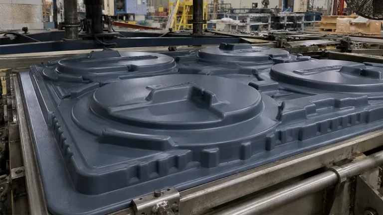
Heavy-gauge thermoforming molds fall into four families: male (plug) molds, female (cavity) molds, matched-die (matching) molds, and pressure-forming molds that add a sealed pressure box on the non-mold side. Each family can be built from wood, epoxy board, cast aluminum or machined aluminum — the family decides part geometry and which surface is finished, while the material decides tool cost, life and cooling.
Male (plug) molds: A male mold is a convex form; the heated sheet is drawn down over it, so the first surface to touch the tool is the part’s inside surface, and that is the surface the mold reproduces crisply. The sheet freezes where it contacts first, so the crown of a male-formed part is its thickest zone and thinning accumulates toward the flanges. Male tooling releases easily once draft is applied and tolerates deep draws with less webbing, which is why it is the default for liners, trays and covers.
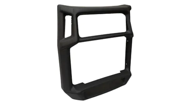
Female (cavity) molds: A female mold is a concave cavity: the sheet is drawn down into it, so the part’s outside surface sits against the tool and carries the mold’s texture or finish. The bottom of the cavity forms last, which makes the mold floor and lower corners the thinnest — and weakest — zones of the part. That thinning is the price of putting the cosmetic surface on the outside, and it is why enclosure parts formed in female tools need generous corner radii and a reviewed draw ratio.
Matched-die (matching) molds: A matched-die mold pairs a male half and a female half, and the sheet is formed by pressing between them rather than by vacuum alone. Thickness distribution is engineered through the die gap instead of emerging from the draw, both surfaces are formed, and ribs or details can be molded in. The costs are higher tooling investment and a need for precise alignment — a misaligned die produces thin spots at the radii that are hard to see before trimming.
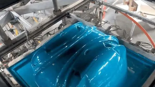
Pressure-forming molds: Pressure-forming molds are female or male tools with a sealed pressure box on the non-mold side. After vacuum draws the sheet, air pressure — commonly a few bar depending on machine and material — pushes it against the mold face, so fine texture, logos and crisp edges reproduce on the mold side. It is the standard route when a formed housing needs an injection-molded appearance without injection tooling cost. The pressure box and sealing add tool cost, so they are justified by cosmetic requirement, not by default.
Our plant runs more than 20 vacuum forming machines processing sheet from 0.5 to 15 mm, with forming lengths up to about 2,500 mm. At the heavy end of that range, tooling stops being a detail: a mold that performs on 2 mm sheet can deflect or leak vacuum when asked to form a 10 mm sheet over a two-meter length. Size the tool for the heaviest sheet you will ever run, not the first.
How Does Mold Shape Decide Wall Thickness and Draft?
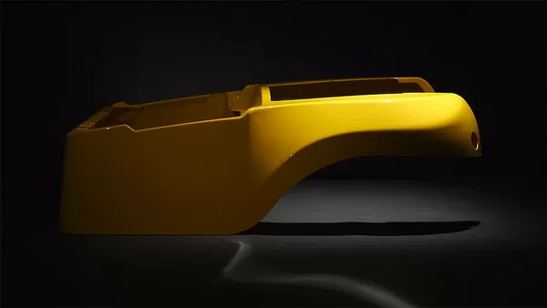
Mold shape sets the sheet’s draw ratio, and draw ratio sets where the material thins. Keep the ratio conservative, apply draft in the 1–3° range, and radius every corner — those three decisions do more for wall uniformity than the choice between vacuum and matched-die tooling.
Draw ratio is forming depth divided by the narrowest opening at that depth. As a working rule, a ratio up to roughly 1:1 is comfortable for straightforward female forming; deeper draws usually want a plug assist or a male tool. The reason is geometric: as the sheet stretches into a deep, narrow cavity, material has to come from somewhere, and the corners and floor pay for it.1
Webbing is the failure mode that shows up between features. On wide flat lands between two raised bosses, the sheet folds instead of stretching, leaving a wrinkle that reads as a defect on the finished wall.2 The countermeasures — feature spacing, radii and a controlled sheet temperature window — belong in the design review, not in trial and error on the tool.
Draft and radii close the geometry. One to three degrees of draft is a common engineering range on formed walls, with textured surfaces wanting the upper end so the texture does not drag on demold.3 Inside radii below roughly the sheet thickness force thinning exactly where the part is already weakest, so most heavy-gauge designs start radii around 1.5–3 mm and scale them with draw depth. The DFM checklist for heavy-gauge thermoformed parts and molds puts these rules in checklist form for drawing review.
"Female molds always produce more uniform wall thickness than male molds."False
A cavity draws the sheet deep before it touches the mold floor, so the bottom and lower corners of a female-formed part are usually the thinnest zones. Male tooling freezes the sheet where it contacts first and protects the crown instead. Uniformity comes from draw depth, plug assist and sheet temperature, not from mold polarity.
"Draw depth, not mold polarity, decides where the part thins."True
The thinnest zone forms wherever the sheet stretches last: a cavity floor, a flange on a male crown, or a radius. Map the last-contacted areas on the drawing and review the draw ratio there, and the thinning question is answered before the tool is cut.
Male or Female Mold: Which Should You Choose?
Choose a male mold when the inside surface is the cosmetic or functional one and the draw is deep; choose a female mold when the outside surface must carry texture, branding or a finished appearance. Move to matched-die or pressure-forming tooling when thickness control or two-sided detail justifies the higher tool cost.
| Criterion | Male (plug) mold | Female (cavity) mold | Matched-die mold |
|---|---|---|---|
| Cosmetic surface | Part inside surface | Part outside surface | Both surfaces formed |
| Thinnest zone | Deep-drawn side walls | Mold floor and lower corners | Controlled by die gap |
| Webbing risk | Lower on deep draws | Higher on deep, narrow parts | Lowest |
| Relative tool cost | Lowest | Moderate | Highest |
| Best suited to | Liners, trays, covers | Enclosures, housings, panels | Structural parts needing thickness control |
The table simplifies. In practice the choice interacts with material: PP and HDPE shrink more and demand more draft whatever the polarity, while PC and PC/ABS hold detail better but punish undercuts. It also interacts with trimming strategy, because the datum the mold establishes is the datum the trim program follows.
Our material library spans ABS, PC, PC/ABS, HDPE, PP and ASA, with formed outputs including ABS seedling trays, PC medical equipment housings and PMMA display covers. Each family shrinks and releases differently — PP wants generous draft and shrink allowance, PC holds detail but resists undercuts — so mold polarity and material have to be reviewed together, not sequenced.
How Does Mold Material Affect Cost and Tool Life?
Wood and epoxy tooling serve prototypes and short runs at the lowest cost; cast aluminum is the production workhorse for vacuum molds; machined aluminum buys tighter detail and dimensional stability at a premium; steel appears mainly in matched-die work. Match the material to sheet temperature and program length, not to volume alone.
Wood tools can be cut in days and modified with hand tools, which makes them ideal for proving geometry. Their limits are moisture movement and surface temperature: a wood mold that holds tolerance for an HDPE liner may drift for a high-temperature material. Epoxy and filled polyurethane board tools give a better surface and longer life at moderate cost, and remain common for mid-volume runs in low-temperature materials.
Cast aluminum puts cooling channels where they belong and handles the sheet temperatures of engineering materials; machined aluminum, cut on multi-axis CNC, adds tighter feature detail and the best dimensional stability. Cooling channel design inside an aluminum tool usually does more for cycle time than any choice between male and female polarity.
Two standards belong in this conversation. ISO 75-2 specifies the heat deflection temperature of plastics under flexural load, and a sheet with a high deflection temperature forms at a higher sheet temperature — which is precisely what disqualifies low-temperature tooling for a PC or PC/ABS housing.4 UL 94 classifies the flammability of plastic materials, and many formed equipment enclosures must meet a specified rating before the design is frozen, which shapes material selection and, in turn, tool material.5
"Aluminum tooling is only justified for high-volume programs."False
Epoxy and wood tools are cheaper up front but move with moisture and heat, and that drift shows up as trimming offsets and assembly gaps. When the part needs stable trimmed accuracy or runs a high-temperature material, aluminum pays for itself well below the volumes buyers assume.
"Mold material should be chosen against sheet temperature and program length together."True
A PC or PC/ABS housing forms at a higher sheet temperature than an HDPE liner, so tooling that holds tolerance for the liner may not hold it for the housing. Compare tool cost against trimming stability, rework and mid-life replacement, not unit volume alone.

What Should You Check Before the Mold Is Approved?
Check the features that cannot be fixed later: vent and vacuum hole placement, cooling circuit layout, datum scheme, and draft on every formed wall. Then judge the tool over a defined initial run with wall thickness measured at fixed landmarks — not on a single first article.
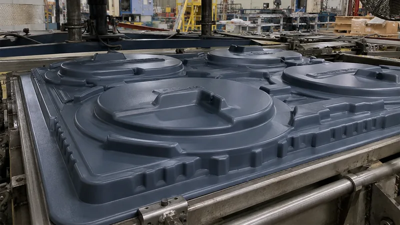
Venting is the quiet failure source. Vacuum holes that are too few or too coarse leave gloss marks or trapped air at fine details, and correcting them in a finished aluminum tool is slow. Agree hole diameter and density per feature before the tool is cut, and record them in the mold specification so the decision survives personnel changes.
Formed parts in our plant are trimmed on a 5-axis CNC centre, and the trimmed outline follows the forming tool. That coupling matters at mold approval: the datum the mold establishes is the datum the trim program inherits, so any post-approval change to the tool silently moves the trimmed outline too.
Sequence the approval the same way every time: dimensional report on the mold, first-off part, process freeze, then the defined run. Skipping the process freeze is the most common shortcut, and it is the one that makes run data meaningless.
"Passing the first article proves the mold is production-ready."False
A first article is one part, from one sheet lot, at one set of process conditions. Sheet gauge variation and process ramp-up both shift wall distribution, so a tool that measures in-spec on piece one can still drift out of tolerance within the first run.
"Tool acceptance should be judged over a defined initial run."True
Freeze the process, then measure wall thickness at fixed landmarks across the run and confirm the trimmed outline holds. A tool accepted this way supports stable monthly volumes; one accepted on a single sample resurfaces later as fit and assembly problems.
FAQ
How long does a thermoforming mold last?
Tool life tracks material and maintenance more than a fixed cycle count. A maintained epoxy tool can run a full mid-volume program in a low-temperature material, while cast aluminum with clean cooling water and correct handling serves multiple programs over years. Ask the molder to state expected tool life against your sheet material and annual volume, with the maintenance interval in writing.
What tolerance can a thermoformed part hold?
As a commercial working range, formed surfaces on mid-size parts are commonly quoted around ±1% of the characteristic dimension, with tighter control achievable on trimmed edges because the outline is cut against the forming tool on a 5-axis centre. Exact capability depends on draw depth, shrinkage and part size, so confirm tolerances zone by zone on the drawing.
Can one mold support different cavity counts or part sizes?
Often, within limits. Multi-cavity tools such as seedling trays are built with a defined cavity count and cell geometry; changing cavity count usually means reworking or adding tool inserts, not adjusting the process. If your volumes vary by product or season, raise this at the mold design stage, because it changes how the tool should be segmented — see thermoforming mold cavities.
Which mold type should I use for an equipment enclosure?
Most enclosure work lands on a female or pressure-forming mold so the outside surface carries the finish, with the sheet material selected for the housing’s safety requirements. If the housing needs crisp edges, visible texture and tight detail, pressure forming earns its tool cost. For a structured comparison of tool styles, see our guide to different types of molds used in vacuum forming.
How does sheet thickness change the mold design?
Heavy-gauge work covers sheet from 0.5 to 15 mm, and the tool feels the top of that range. Thick sheet needs more heat input, stronger clamping, larger radii and more robust venting, and on long parts — forming lengths up to about 2,500 mm — mold rigidity and uniform cooling across the tool surface become the governing design issues rather than detail sharpness.
To keep exploring how tooling choices shape the finished part, walk through our vacuum forming process overview or see how our heavy-gauge forming capabilities are organized around tooling, materials and trimming. Both go a level deeper than this guide.
-
Draw ratio: The forming depth of a part divided by its narrowest opening at that depth; it estimates how much the sheet must stretch during forming. ↩
-
Webbing: Wrinkles or folds that form when the sheet bridges between raised features instead of stretching, appearing as defects on the finished wall. ↩
-
Draft angle: The taper applied to formed walls so the part releases from the mold without dragging or distorting the formed surface. ↩
-
HDT: Heat deflection temperature, the temperature at which a plastic specimen deflects a defined amount under flexural load. ↩
-
UL 94: The flammability classification standard for plastic materials, used to qualify materials for electrical enclosures and housings. ↩