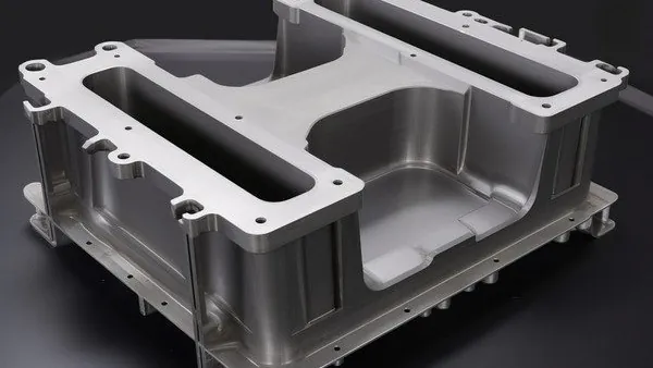
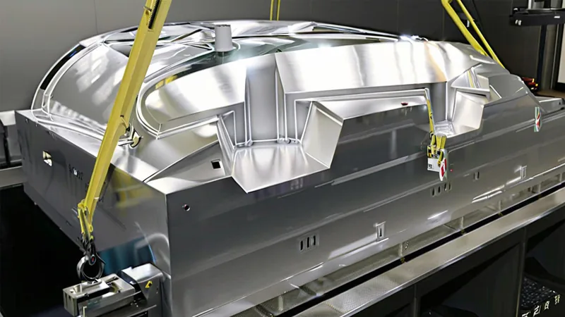
Mold design decides the outcome of a heavy-gauge thermoforming project long before the first sheet is heated. The machine matters, but the tool determines how the plastic stretches, where the walls thin, and whether parts trim and assemble cleanly. This guide covers the engineering decisions behind a vacuum forming mold: mold side, mold material, vacuum hole layout, draft and shrinkage, and the checks that qualify a tool for production.
- The mold side decides which surface carries cosmetic detail and critical dimensions.
- Machined aluminum suits production tools; cast, epoxy, and wood tools serve prototyping and short runs.
- Vacuum hole size, count, and placement control sheet conformity and surface marking.
- Draft, corner radii, and shrinkage allowance must be engineered before the tool is cut.
- Wall-thickness mapping across several cycles, not a single first article, qualifies a mold.
- Material standards such as ASTM D638 and UL 94 anchor the part validation plan.
What Does a Thermoforming Mold Actually Control?
A thermoforming mold shapes heated plastic sheet under vacuum and fixes the three variables that dominate part quality: wall-thickness distribution, surface detail, and dimensional repeatability. Everything else on the machine — heater zones, vacuum flow, cycle timing — is tuned around what the tool allows.
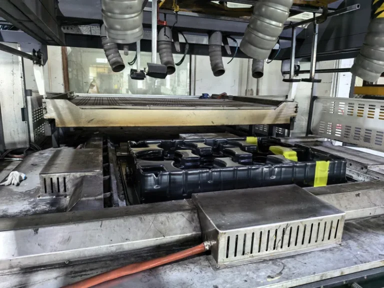
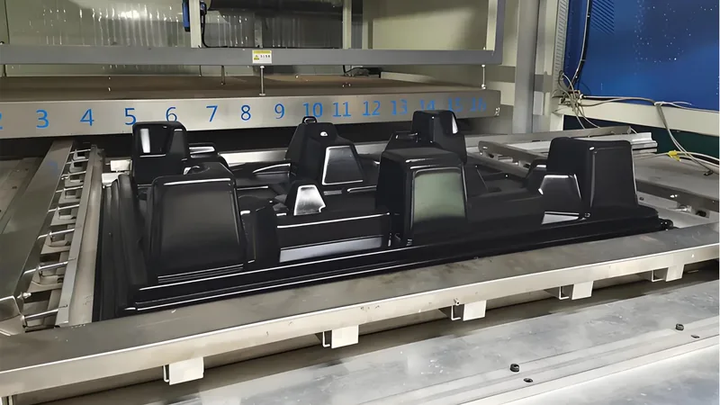
In vacuum forming, atmospheric pressure presses the softened sheet against the mold once the air between them is evacuated. The tool therefore has two jobs at once: define the geometry and manage the air. Geometry gets all the attention in CAD, but air management — hole placement, vent paths, sealing surfaces — separates a crisp part from one with thin corners or bubble marks. On heavy-gauge work, where sheet runs from roughly 0.5 mm to 15 mm thick, the extra thermal mass makes these details even less forgiving.
The tool also carries the details that never appear in the 3D model: trim datums, clamping frames, sheet seals, and the registration features that position the part after forming. A mold that forms beautiful parts but leaves no clean trim reference will slow every downstream step, which is why experienced designers treat the trim plan as part of mold design from day one.
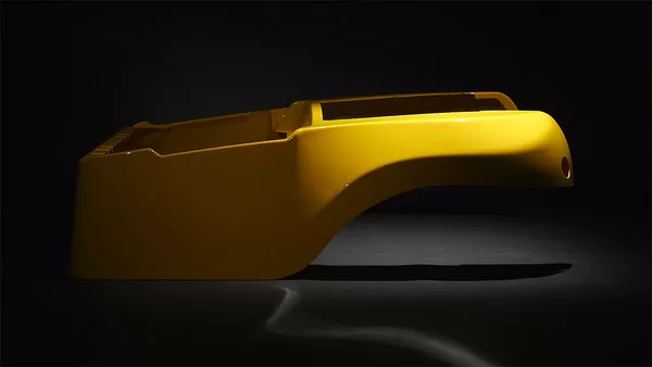
ZetarVac processes sheet from 0.5 to 15 mm thick and forms parts up to about 2,500 mm long. At that size, the mold — not a machine setting — is what keeps a large panel dimensionally predictable, because every extra metre of forming length multiplies the effect of thinning and uneven cooling built into the tool.
Male or Female Mold: Which Side Should Form Your Part?
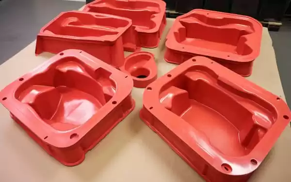
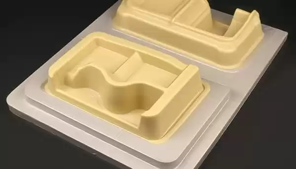
A male (positive) mold gives the most accurate inside surface and stretches the sheet more evenly over deep draws. A female (negative) mold puts detail and texture on the outside surface but thins the sheet where it pools into corners. Choose the side that carries your critical dimensions and cosmetic face.
In practice the decision starts with one question: which surface does the part specification actually measure? Deep trays and covers that locate on inside features usually start on a male tool, because the inside surface contacts the mold directly and holds dimension. Equipment housings and cosmetic panels usually start on a female tool, because grain, texture, and outside radii form against the tool surface.
The trade-off is thinning. On a female tool the sheet bridges the cavity first and touches the bottom last, so the bottom centre is the thinnest region of the part. On a male tool the thinnest zone shifts to the sides of tall features. A capable mold designer predicts that map before cutting metal; our comparison of positive and negative thermoforming molds walks through the full trade-off.
"A female mold always produces better-looking parts than a male mold."False
Cosmetic quality depends on which surface touches the tool, not on the mold type itself. A female tool marks the outside but thins the part bottom, while a male tool can deliver a clean visible surface where no fine outside texture is required.
"The mold side must match the surface that carries critical dimensions."True
Inside-critical parts belong on male tools and outside-critical parts on female tools. Getting this backwards forces tolerance disputes and secondary machining that the right tool orientation would have avoided.
Which Mold Material Matches Your Volume?
Machined aluminum is the default for production because it conducts heat quickly, holds tolerance, and survives long-running cycles. Cast aluminum, filled epoxy, and wood or composite patterns cover prototyping and short runs at a fraction of the cost. Match tool life to program volume, not the other way around.
The economics are straightforward. A production aluminum tool costs more up front and pays it back over large batches through cycle consistency and dimensional stability. A prototype tool exists to answer design questions — does the geometry form cleanly, does the assembly fit, where does the wall thin — and a fast, inexpensive material answers those questions better than waiting for a production tool. Many programs run both: a prototype tool to freeze the design, then a production tool cut from the validated geometry. For early-stage work, cast and plaster-based prototype molds deserve a closer look.
Heat control is the quiet advantage of metal tools. Aluminum pulls heat out of the sheet quickly and evenly, which shortens cycles and reduces residual stress in the part, while low-conductivity prototype materials form parts that cool slowly and may show more warp. Production tools therefore add cooling channels or internal water lines, and their layout is part of mold design: uneven cooling shows up later as bow on large flat panels and as distortion around heavy rib clusters.
| Mold material | Typical use | Relative tooling cost | Heat control | Best suited for |
|---|---|---|---|---|
| Machined aluminum | Production tooling | High | Excellent, zone-controllable | Long runs, tight tolerances, large parts |
| Cast aluminum | Medium volume, complex geometry | Medium | Good | Cast-in detail, textured faces, undercuts |
| Filled epoxy / composite | Pilot and prototype | Low | Moderate | Design validation, short batches |
| Wood / pattern board | Concept models | Lowest | Poor | First shape and fit checks |
ZetarVac supports prototyping, small batch, and large batch production in the same plant, with 20+ vacuum forming and thermoforming machines. That means the tool material can be matched to each stage — a fast prototype tool to prove the geometry, then an aluminum production tool — without changing suppliers or requalifying the design.
Where Should Vacuum Holes and Venting Go?
Vacuum holes belong in valleys, corners, and along the last surfaces the sheet touches — not on visible cosmetic faces. Heavy-gauge tools typically use holes of roughly 0.5–1.5 mm, small enough to leave no witness mark but dense enough to evacuate air quickly from deep pockets.
Placement matters more than quantity. A useful habit is to map where the sheet contacts the tool last and cluster holes there: inside corners, the bottom of deep pockets, and the far side of tall ribs. Spacing in those zones is often kept in the 20–50 mm range, while large open flats need few or no holes.
Male tools add a second requirement — venting the air trapped as the sheet collapses over the form — so vents on a male tool usually outnumber those on a female tool for the same part. Hole edges are chamfered so the sheet seals smoothly instead of snagging, and any hole that would sit on a cosmetic face is moved or replaced with a narrow slot hidden inside a trim zone.
Multi-cavity tools raise the stakes further: air paths must be balanced so every cavity forms at the same rate, or parts will vary from cycle to cycle. Our guide to thermoforming mold cavities explains how cavity count interacts with vacuum flow and sheet width.
How Do Draft, Shrinkage, and Webbing Get Designed Out?
Add roughly 1–3 degrees of draft on formed walls, allow for shrinkage of roughly 0.3–0.8 percent depending on the resin, and use generous corner radii so the sheet stretches instead of bridging. These three allowances are cheap to design in and expensive to retrofit.
How draft and release interact. A formed part shrinks as it cools, which grips a male tool and releases from a female tool. That is why male tools need working draft1 of roughly 1–3 degrees on deep walls — more on textured surfaces — while female tools are somewhat more forgiving. Undercuts on either tool type call for movable sections or a design change, and every degree of draft added in CAD is cheaper than the rework that poor release produces at the machine.
Shrinkage and dimensional planning. Resins contract as they cool, so the tool is dimensioned larger than the final part by the shrinkage factor of the chosen material. The exact figure belongs to the resin grade and sheet gauge, and parts formed at 15 mm gauge behave differently from thinner work in the same resin, so the value is confirmed with trial formings rather than assumed from a handbook alone.
Webbing and radius control. Webbing2 — unwanted material bridges between tall, closely spaced features — is a geometry problem before it is a machine setting. Widening the gap between features, opening inside corners, and using radii of at least one sheet thickness on both male and female tools removes most webbing before it forms. Where the design cannot change, the mold designer relocates the web into a zone that trims away later.
How Is a New Mold Qualified Before Production?
Qualify a tool with a documented plan: map wall thickness across several cycles, verify trimmed dimensions on the production trim process, and run the material tests the part specification calls for. A good first article proves the mold can work; the qualification plan proves it will work every cycle.
Wall-thickness mapping is the core check. Formed parts thin predictably but not uniformly, so a grid of measured points — bottom centres, side walls, radius zones — is compared against the design minimums on parts taken from consecutive cycles. For structural parts, ASTM D638 specifies the standard tensile test used to characterize plastic sheet and formed parts, and running it on samples cut from formed parts confirms that forming and cooling have not degraded the strength the design relies on.
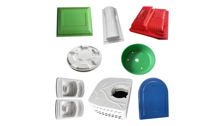
For formed equipment housings and covers, UL 94 defines the flammability classifications many electrical enclosures must meet3, so the resin grade and its documentation must be settled before the tool is cut. A mold cannot add fire performance the sheet does not have.
Service temperature belongs in the same conversation: the heat deflection temperature4 of the resin sets the upper working limit of the part, and it constrains material choice long before mold geometry is finalized.
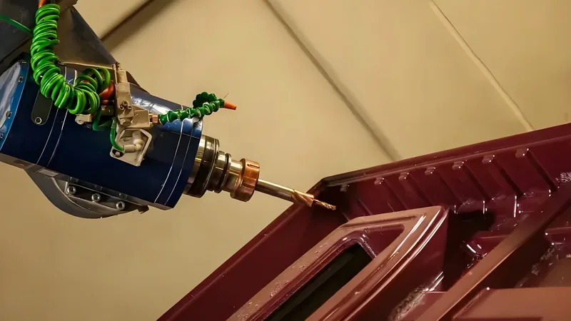
ZetarVac trims formed parts on a 5-axis CNC centre, and the trimmed outline follows the forming tool. Trim datums and reference features therefore belong inside mold design: a tool planned without them forces every downstream trim and assembly step to improvise.
Sheet and mold interact during qualification as well. The same tool can produce different thickness maps on different resin grades, so the plan is run with the production resin and gauge, not a convenient stand-in. Any later change of resin grade, gauge, or sheet supplier is treated as a process change and triggers a short requalification run.
"A good first article means the mold is ready for volume production."False
A first article is often formed with extra care and generous cycle time that a production schedule will not allow. Wall distribution shifts with heater state and sheet lot, so the mold is qualified only after thickness maps repeat across consecutive cycles.
"Wall-thickness mapping across several cycles is the real mold acceptance test."True
Measuring the same point grid on parts from consecutive cycles shows whether the tool, the heating profile, and the vacuum path are stable together. Only then are the process parameters locked and the tool released for volume.
FAQ
How much does a thermoforming mold cost?
Tooling cost scales with mold material, part size, cavity count, and surface detail. A prototype tool is typically a fraction of a machined-aluminum production tool, and the fair comparison is total tool life against program volume rather than the initial invoice.
How long does a mold take to design and build?
Prototype tools are usually measured in days to weeks; production aluminum tools take longer because of machining, polishing, and vacuum-hole drilling. The schedule depends mainly on part size, geometry complexity, and how early the design is frozen.
Can one mold handle several sheet thicknesses?
A tool is normally tuned to one gauge or a narrow range, because shrinkage, radii, and hole layout all interact with sheet thickness. Forming the same geometry at a different gauge usually requires a trial run and possible tool adjustments.
What should you give a mold designer before the project starts?
A 3D model with critical dimensions called out, the resin and sheet gauge, cosmetic faces, expected volumes, and any regulatory requirements. The more complete this package is, the fewer costly revisions the tool needs later.
When is pressure forming worth the extra tooling cost?
Pressure forming adds air pressure on top of vacuum, which sharpens texture and fine detail on the female tool surface. It earns its cost when the outside surface needs crisp lines or texture that vacuum forming alone cannot reproduce.
To keep digging into how mold decisions shape formed parts, explore the ZetarVac vacuum forming process guide, or walk through the China vacuum forming manufacturer page to see how large-format forming and 5-axis trimming capability support demanding tooling projects.
-
Draft angle: The slight taper added to mold walls so a formed part releases cleanly instead of gripping the tool. ↩
-
Webbing: Unwanted material bridges that form between tall or closely spaced features when the sheet stretches unevenly. ↩
-
UL 94: A flammability standard that classifies plastic materials by their burning behavior, commonly specified for electrical equipment enclosures. ↩
-
Heat deflection temperature: The temperature at which a plastic specimen deflects a defined amount under flexural load, used to judge the upper service temperature of a formed part. ↩