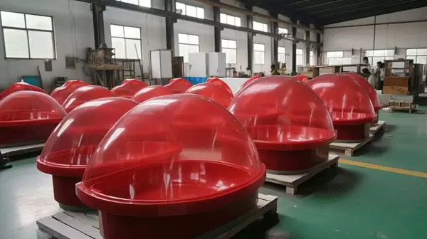
Plastic vacuum forming converts a flat thermoplastic sheet into a large, three-dimensional part using heat, a single-sided mold, and vacuum pressure. It is the process behind equipment housings, machine covers, industrial trays, medical enclosures, and retail display covers — large plastic parts produced in volumes that never justify matched-metal tooling. This guide explains what the process is, how a heavy-gauge forming cycle runs stage by stage, when pressure forming earns its cost, which sheet materials to specify, what tolerances formed parts hold, and how finished parts are tested before acceptance.
- Vacuum forming is a thermoforming process: a heated thermoplastic sheet is drawn against a single-sided mold by vacuum, then cooled and CNC-trimmed to its final outline.
- Only the mold-side surface carries fine detail and tight radii; the free surface follows the sheet’s own wall-thickness distribution.
- Industrial heavy-gauge lines process sheet from 0.5 to 15 mm and form parts up to about 2,500 mm long, finishing on 5-axis CNC trimming centres.
- Formed wall thickness is a distribution, not a constant; the thinnest zone governs strength and must be measured on the finished part.
- Specify the resin for the service environment first — ABS, PC, PVC, HDPE, PP, PMMA — then tune the forming window around it.
- Acceptance combines flammability, mechanical, and thermal testing with dimensional checks on fully cooled parts.
What Is Plastic Vacuum Forming?
Plastic vacuum forming is a thermoforming process that converts a flat thermoplastic sheet into a three-dimensional part: the sheet is clamped, heated until pliable, and drawn against a single-sided mold by vacuum. Once it cools and holds its new geometry, the part is trimmed to its final outline.
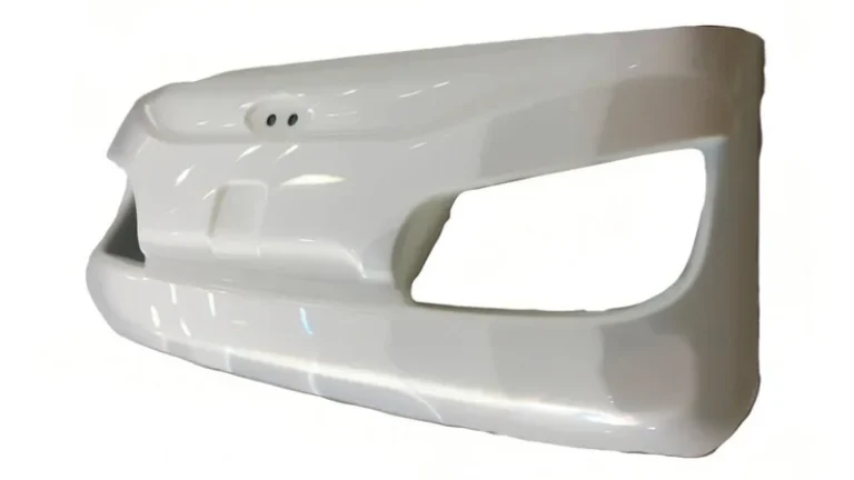
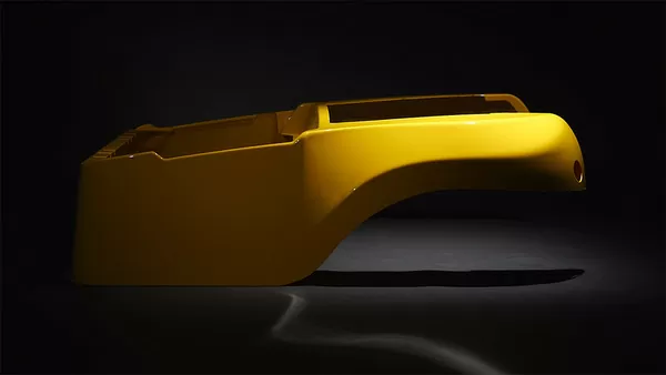
In heavy-gauge industrial work, the process produces large structural and cosmetic parts — equipment housings, machine covers, industrial trays, medical enclosures, and retail display components. The defining feature is the single-sided tool. Only one mold surface defines the part, so tooling cost and lead time stay low, and geometry can be revised between production runs at modest cost.
The trade-off is asymmetry. The side touching the mold carries fine detail and tight radii, while the free surface follows the sheet’s own formed wall distribution. Designers who respect that asymmetry get parts that form predictably; those who ignore it get webbing, thin corners, and flanges that will not sit flat. For capability ranges and part families, see our vacuum forming overview.
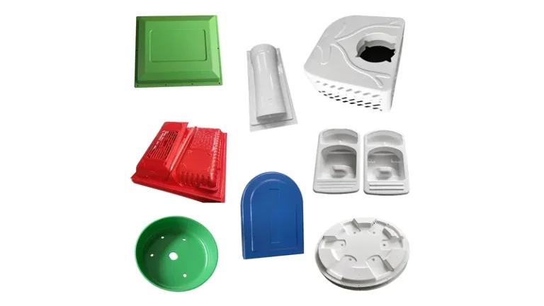
In industrial production, heavy-gauge formed parts dominate wherever a large plastic component is needed in moderate volumes: equipment housings and machine covers, material-handling trays, protective guards, vehicle interior panels, and retail display components across agricultural, medical, industrial, logistics, and consumer markets.
Three production cases show the range. An ABS vacuum-formed seedling tray for agricultural use is formed as a multi-cavity part with custom cell geometry and tray size, then trimmed and stacked by the thousand. A PC vacuum-formed medical equipment housing shows the process at its most demanding: a large, complex curved shell with custom cut-outs, mounting holes, and reinforcement formed in one piece. A PMMA display cover covers the cosmetic end — a high-clarity curved cover protecting retail product while keeping it fully visible. To see how these part families map onto industries and project types, review our integrated service overview.

Our plant runs 20+ vacuum forming and thermoforming machines processing sheet from 0.5 to 15 mm, with a maximum forming length of about 2,500 mm. For a project team, that means a single formed panel can span a full machine frame without seams, and the same process discipline covers thin liners and thick structural enclosures.
With 45+ production lines across the plant and a reference monthly capacity of roughly 100,000 to 200,000 pieces, prototyping, small batch, and large batch production are all supported within the same process. A buyer can start with a pilot tray or housing and scale to serial volumes without changing supplier or forming route.
How Does the Vacuum Forming Process Work, Step by Step?
Every heavy-gauge cycle, regardless of machine size, moves through five stages: clamping, heating, forming, cooling, and trimming. What separates a controlled process from an improvised one is how tightly each stage is instrumented and repeated across sheet lots.
Clamping and heating. The sheet locks into a frame and travels under radiant heaters. Sheet temperature is the most sensitive variable in thermoforming: too cold and the sheet will not draw into corners; too hot and it sags uncontrollably or thins at the deepest draw. Practical forming temperatures sit near 130–180 °C for ABS and 170–210 °C for PC as common engineering ranges, but the real control signal is sag depth, which operators watch rather than trusting setpoints alone, because gauge, color, and lot variation all shift how the sheet absorbs heat.
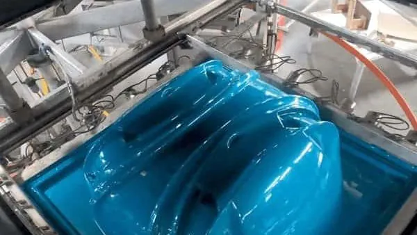
Forming under vacuum. When the sheet reaches its forming window, it is sealed over the mold and vacuum is pulled. Atmospheric pressure — roughly one bar at sea level — does the actual work, so forming speed depends on how quickly and how deeply the vacuum is drawn. Deep draws add a pre-stretch bubble or a plug assist to keep material where the part needs it, and vent holes drilled through the mold let trapped air escape so the sheet picks up every rib and radius instead of bridging over them.
Cooling and release. The part must cool below the material’s heat deflection temperature before release, or residual stress and sheet memory will pull it out of shape1. Fans, water mist, or chilled tool surfaces shorten this stage. Rushing it is the most common cause of warped panels and bowed flanges.
Trimming and finishing. Formed parts leave the mold oversize and are cut to final outline on a 5-axis CNC trimming centre, where the trimmed outline follows the forming tool datum2. One setup turns a formed shell into a finished housing with cut-outs, mounting holes, and clean edges.
"A thicker starting sheet always makes a stronger formed part."False
Forming redistributes material, so the wall thins wherever the sheet stretches most — usually at deep draws and sharp corners. Starting thicker does not prevent local thinning, and very thick sheet heats unevenly, which makes thinning less predictable. A part can fail at a 1 mm corner while the nominal sheet is 10 mm.
"Formed wall thickness must be verified on the finished part, not on the sheet certificate."True
The sheet certificate states the incoming gauge, but forming changes the thickness distribution across the part. Ultrasonic gauging or cut-section checks at the known high-stretch zones are the only meaningful confirmation. A capable supplier identifies those zones during development and adds them to the routine inspection plan.
Vacuum Forming or Pressure Forming: Which One Fits Your Part?
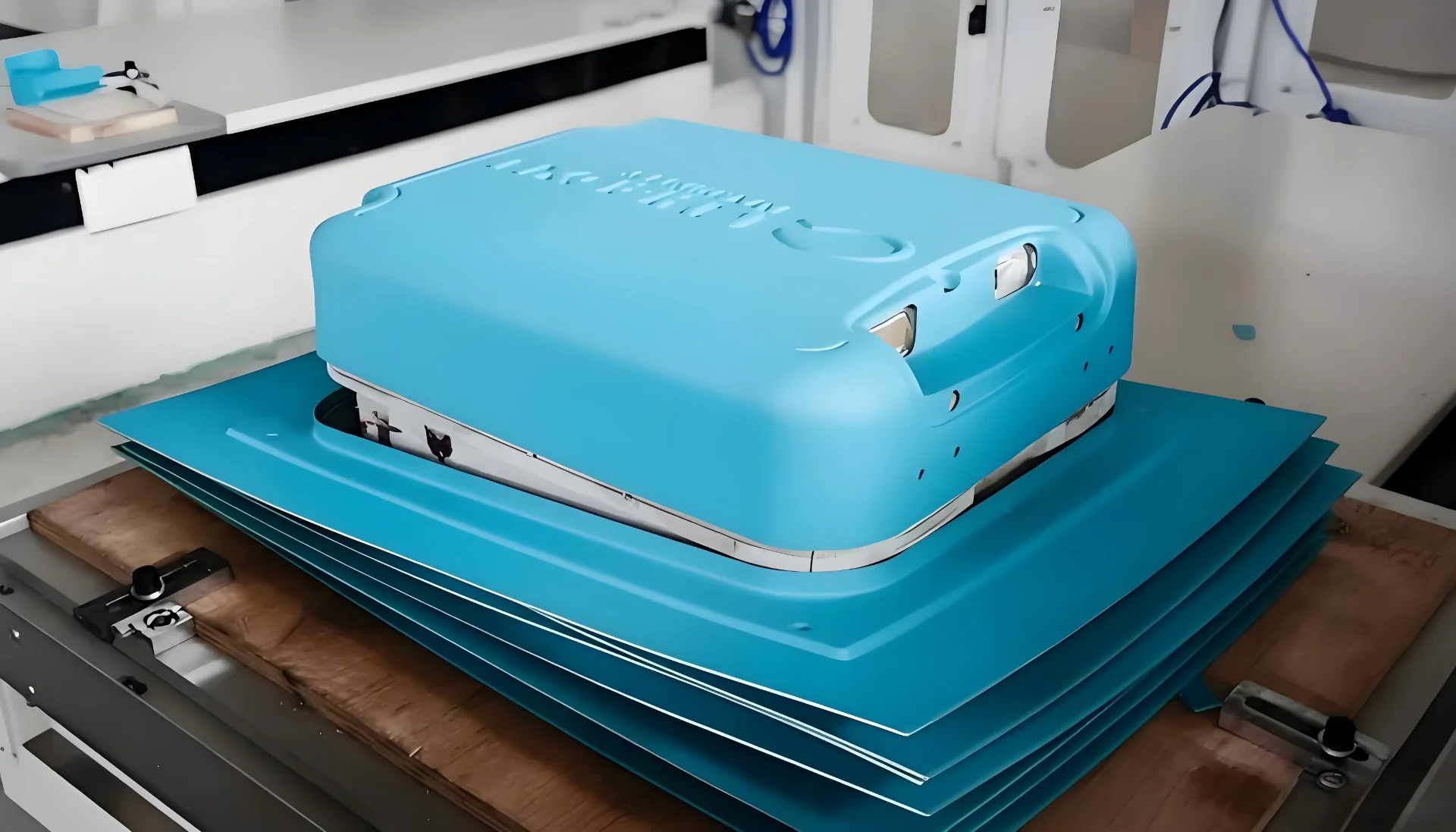
Both processes heat a plastic sheet and form it over a single-sided mold, but they use different driving forces: vacuum forming pulls the sheet down with vacuum alone, while pressure forming adds compressed air above the sheet. The choice comes down to free-surface detail requirements and tooling budget.
For most industrial heavy-gauge parts — housings, trays, liners, guards — vacuum forming delivers the required geometry with simpler, cheaper tooling. Pressure forming earns its cost on cosmetic surfaces: sharper texture definition, crisper lettering, and tighter radii on the side that never touches the mold. The comparison below shows where each process wins.
| Criterion | Vacuum forming | Pressure forming |
|---|---|---|
| Driving force | Vacuum, about one bar, on the mold side | Vacuum plus compressed air above the sheet |
| Tooling complexity | Single-sided mold with vent holes | Pressure box, seals, and a stiffer mold |
| Free-surface detail | Follows the sheet; softer radii | Sharper texture, lettering, and radii |
| Typical heavy-gauge parts | Housings, trays, liners, guards, covers | Cosmetic front panels, bezels, fascias |
| Relative tooling cost | Lower | Higher |
Which Sheet Material Should You Specify?
ABS, PC, PVC, HDPE, PP, and PMMA cover most heavy-gauge applications because they combine formability with predictable service properties. Choose the resin for the service environment first; the forming window is then tuned around the material.
Each resin has its own forming window — the temperature band where the sheet sags evenly, draws without tearing, and releases without sticking. PC and PMMA demand tighter temperature control than ABS; PP has strong sheet memory and needs deliberate cooling; HDPE shrinks noticeably and affects any tolerance written on the drawing. Gauge matters too: thin sheet under 2 mm suits packaging and liners, mid gauges from 3 to 8 mm serve housings and trays, and heavy sheet above 10 mm behaves closer to a structural panel, with heater dwell and cooling time dominating the cycle.
| Material | Typical formed applications | Specify it when you need |
|---|---|---|
| ABS | Equipment housings, cases, guards, automotive interior parts | Balanced impact strength and a forgiving forming window |
| PC | Clear guards, equipment protection covers, automotive parts | Transparency combined with high impact resistance |
| PC/ABS | Automotive interiors, equipment housings, guards | Heat resistance and toughness in one blend |
| PVC | Trays, packaging, industrial enclosures, liners | Cost-effective forming with chemical resistance |
| HDPE | Industrial trays, equipment liners, storage boxes | Chemical and abrasion resistance at low cost |
| PP | Trays, boxes, automotive interior parts, equipment liners | Chemical resistance in a lightweight part |
| PMMA | Clear covers, luminaires, display parts, retail displays | Optical clarity and outdoor weathering |
| ASA | Outdoor equipment housings, automotive exterior parts | UV stability without painting |
| PP/GF | Automotive and industrial structural parts | Stiffness beyond unfilled sheet |
| TPE / TPV / TPU | Soft liners, seals, flexible sleeves, protection parts | Elastomeric function formed in one piece |
"Any thermoplastic sheet forms well with the same heater settings."False
Each resin has its own forming window, and PC, ABS, PP, and PMMA differ in sag temperature, sheet memory, and cooling shrinkage. Reusing settings across materials produces webbing, blisters, incomplete detail, or warped flanges. The window must be re-established whenever the material, gauge, or sheet lot changes.
"Material selection should follow the service environment before the forming window."True
Impact, heat, transparency, UV, and chemical exposure are properties you cannot recover after forming, while the forming window is something a competent molder tunes per material. Choosing a resin because it is easy to form usually ends with a part that fails in the field.

What Tolerances Can a Vacuum Formed Part Hold?
A formed part carries two tolerance layers: the incoming sheet gauge variation and the thinning introduced by forming itself. Flat areas and CNC-trimmed features hold tighter limits than deep-drawn walls, where thickness can drop by a substantial fraction depending on draw depth, radii, and material.
Mold shrinkage adds a third layer. Each resin contracts as it cools, and the contraction differs between the machine direction and cross direction of the sheet, so a molder who knows the material compensates the tool accordingly. ABS, HDPE, and PP sit at clearly different points on the shrinkage scale, which is one more reason material selection belongs at the start of the drawing review.
Formed parts on our floor are trimmed on a 5-axis CNC trimming centre, and the trimmed outline follows the forming tool. Because cutting and forming share the same datum, hole-to-edge relationships stay consistent from the first part to the last in a batch — the condition that matters most when housings must mate with machine frames or electronics.
How to structure a tolerance scheme. Split the drawing’s dimensions into three groups: mold-controlled surfaces, trimmed features, and free-formed walls. Negotiate tight limits only where they are functionally needed — mounting holes, sealing surfaces, mating edges — and state formed wall thickness as a distribution instead of a single number. Every measured feature then has a limit it can realistically meet, and inspection stays honest.
"Passing the first article guarantees the whole batch will match it."False
A first article is a snapshot of one sheet lot, one heater condition, and one ambient temperature. Sheet lots, heater aging, and seasonal humidity all shift shrinkage and thickness distribution across a run. Without periodic in-process checks, a batch can drift out of tolerance while the first article report still sits in the file.
"Formed parts should be dimensioned only after they fully cool to room temperature."True
Thermoformed parts continue to shrink and relax as they settle to room temperature, and post-forming movement can continue for hours on materials with high sheet memory. Measuring a warm part gives optimistic dimensions that will not survive. Fixing which features are checked, when, and at what part temperature is part of a proper acceptance plan.
How Are Vacuum Formed Parts Tested and Accepted?
Validation combines material-level tests on sheet or part with dimensional and functional checks on the finished assembly. For most formed industrial parts, three test families carry the most weight: mechanical strength, flammability, and ingress protection.
Tensile testing per ISO 527-2 — the standard tensile test run on thermoformed sheet — confirms that the material delivers the strength and elongation the design assumed, and it applies equally to specimens cut from formed parts3. For housings that surround electrical equipment, flammability comes first. UL 94, the standard for the flammability of plastic materials, classifies how a specimen extinguishes after a controlled flame exposure, and it is required for many equipment enclosures; a formed cover specified at a given UL 94 rating must be made from sheet certified to that rating4.
Where a formed enclosure is sold as an ingress-protected cover, IEC 60529 defines the IP code system that grades protection against dust and water, and the flange and gasket design must be engineered to meet the declared rating5.
A sensible plan matches tests to risk. A seedling tray needs geometry, drainage, and material checks, while a medical equipment housing needs flammability documentation, dimensional verification of cut-outs and mounting holes, and a thickness survey at its deepest draws. For a neutral description of the forming process itself, the CustomPartNet thermoforming reference is a useful starting point before comparing supplier-specific capabilities.

FAQ: What Engineers and Buyers Ask About Vacuum Forming
Is vacuum forming the same as thermoforming?
Thermoforming is the family name for all sheet-forming processes; vacuum forming is its most common member, distinguished by using vacuum rather than added air pressure to drive the sheet against the tool. In heavy-gauge industrial work, the two terms are used interchangeably for the same process.
How thick can the sheet be?
Industrial heavy-gauge lines routinely process sheet from 0.5 to 15 mm and form parts up to about 2,500 mm long. Above roughly 10 mm, heater dwell and cooling time dominate the cycle, so thick structural parts need a molder whose machines and tool design are sized for that gauge range.
How strong is a vacuum formed part?
Strength comes from the material plus the thinnest formed wall, not from the process label. When ribs are designed into the tool and wall distribution is verified on the part, formed housings and trays carry real structural loads — which is why they serve industrial equipment, vehicles, and logistics systems for years.
Can vacuum forming support prototypes and low volumes?
Yes. Prototyping, small batch, and large batch production are all supported within the same process. Because production tooling is single-sided and comparatively inexpensive, a pilot run of dozens of parts is a normal request rather than an exception.
What should I prepare before a supplier technical review?
Bring the service environment — temperature, load, UV or chemical exposure — the largest part envelope, the mating interfaces, and any compliance requirement such as flammability rating or optical clarity. With those fixed, a molder can propose material, gauge, and a tolerance scheme in the first technical exchange instead of guessing.
To keep digging before you compare suppliers, explore our vacuum forming capability guide for process details and part families, or review how a China vacuum forming manufacturer organizes tooling, forming, and trimming under one roof. Both will help you ask sharper questions at the procurement stage — before anyone talks numbers.
-
HDT: Heat deflection temperature is the temperature at which a plastic specimen deflects a defined amount under a specified flexural load, tested per ISO 75-2 or ASTM D648; formed parts must cool below it before release. ↩
-
5-axis CNC trimming: A machining process in which the cutting head moves along five axes simultaneously, trimming formed parts to their final outline against the forming tool datum. ↩
-
ISO 527-2: The part of ISO 527 that specifies the tensile test method for plastics, widely run on thermoformed sheet and on specimens cut from formed parts. ↩
-
UL 94: The Underwriters Laboratories standard for the flammability of plastic materials, classifying how specimens extinguish after flame exposure; required for many equipment enclosures. ↩
-
IP code: The ingress protection classification defined by IEC 60529, grading enclosures for protection against dust and water intrusion. ↩