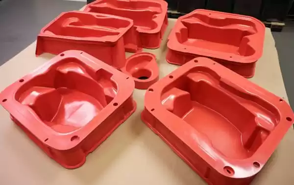
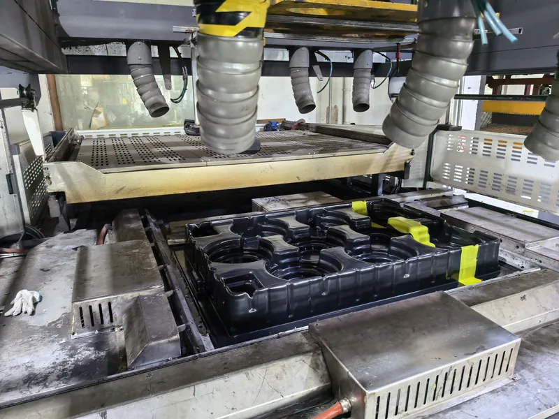
When sourcing heavy gauge thermoforming, buyers quickly face a design decision that shapes tooling cost, assembly labor, and quality risk: should the product be formed as a single large shell, or split into several vacuum formed parts that are trimmed and joined later? The answer is rarely about size alone. Draw depth, thickness distribution, tolerance stack-up, and trimming strategy decide which route survives production. This article breaks down the engineering differences between one piece and multi piece vacuum formed parts, where each approach wins, how each fails, and what to verify before release.
- A one piece vacuum formed part removes assembly joints, but concentrates thickness variation in deeply drawn zones.
- A multi piece design trades extra molds and assembly fixtures for shallower draws and easier trimming.
- Tolerance follows the draw: clamped flange areas hold closer limits than stretched corners, regardless of part count.
- Splitting a design does not automatically cut cost, because molds, trim fixtures, and fasteners add up quickly.
- Validate either approach across sheet lots with tensile and heat deflection testing, not a single first article.
- With a maximum forming length of about 2,500 mm, many enclosures can stay one piece even at industrial scale.
What Defines a One Piece Vacuum Formed Part?
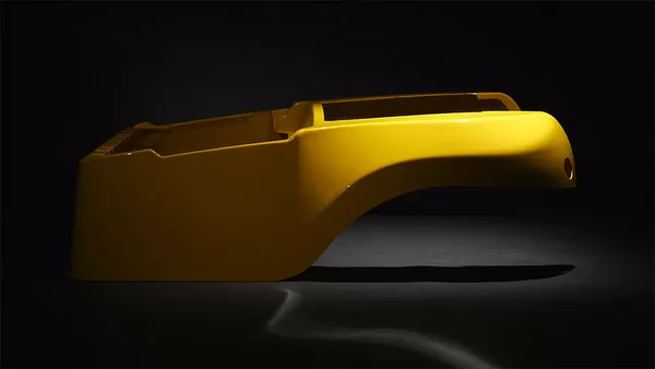
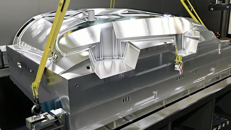
A one piece vacuum formed part is produced from a single heated sheet drawn over one mold, then trimmed into a complete shell. All geometry the sheet can reach within one forming cycle is built into a single tool, and nothing needs to be aligned, fastened, or sealed afterward.
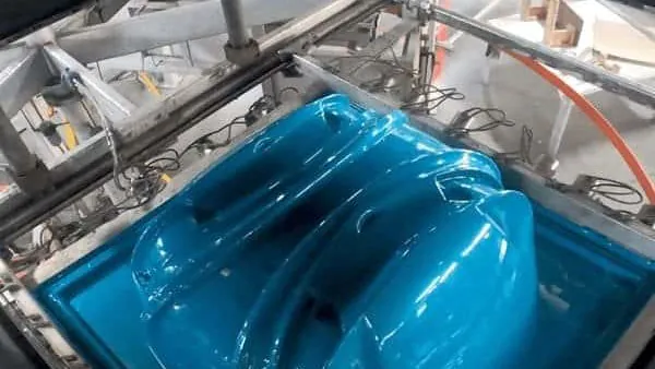
In heavy gauge thermoforming, the starting sheet commonly runs from 0.5 to 15 mm thick. The critical variable is the draw ratio1. As the sheet stretches into deeper cavities, wall thickness drops from the original gauge, with thinning concentrated in corners and vertical walls. Clamped areas near the flange stay close to sheet thickness, while deeply drawn floors can lose a large share of it. Draft angle2 design matters here too, because insufficient taper forces the sheet to drag and thin unevenly against the mold.
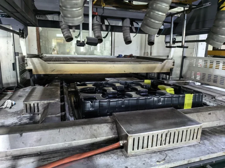
ZetarVac processes sheet from 0.5 to 15 mm with a maximum forming length of about 2,500 mm, supported by more than 20 vacuum forming machines. For an equipment housing or machine enclosure that fits inside that envelope, a one piece shell is usually the lower-risk route because it removes seams, fasteners, and alignment work from the assembly.
When Does a Multi Piece Vacuum Forming Strategy Make Sense?
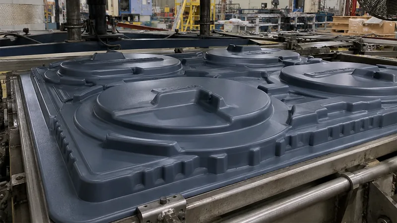
A multi piece strategy makes sense when one tool cannot reach the geometry, when deep draws would thin walls below specification, or when handling, shipping, and maintenance require separable sections. Splitting converts one difficult draw into several easy ones.
Typical triggers include side geometry that a straight vacuum pull cannot form without undercuts, sharp detail in areas where webbing3 would bridge across male mold peaks, and enclosures large enough that a single shell becomes impractical to trim, ship, or service. A control cabinet might become a formed base plus a formed cover, each with its own trim line and fastening flange. Where a split looks unavoidable, the undercut design guide explains how to keep release geometry workable on a single mold before committing to two.
The trade is a new set of interfaces. Flange flatness, fastener patterns, and sealing now belong to the assembly drawing, and each formed component must locate reliably against the next. The reward is part-level repeatability: each shallow draw holds its shape more predictably than one aggressive draw, and individual sections can be replaced in service without scrapping the whole enclosure.
How Do Draw Depth and Thickness Variation Affect Tolerances?
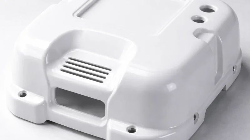
Depth drives thickness, and thickness decides what a formed feature can hold. Clamped flange zones keep close to sheet gauge, drawn side walls thin progressively, and corners thin most, so the tightest tolerances belong in the areas the sheet reaches with the least stretch.
"A one piece part always holds tighter tolerances because it has no assembly joints."False
Fewer joints help at the interfaces, but a deeply drawn one piece shell still distributes thickness unevenly, and thin, highly stretched zones drift more in service. The consequence is a part that is dimensionally a single piece yet varies most exactly where precision is needed.
"Tolerance capability depends on feature location relative to the draw, not on part count alone."True
Features near the clamped flange stay close to the original sheet gauge, while features on deep draws inherit thinning and springback. Evaluate limits feature by feature on the drawing, and assign critical dimensions to low-strain zones wherever the design allows.
For a multi piece assembly, each component adds its own variation, and the stack-up across joints decides the final fit. That does not make multi piece worse; it makes the flange and fastener scheme a tolerance-critical design element. Specify assembly datums on the formed parts themselves, so stack-up can be measured on real components instead of assumed on the drawing.
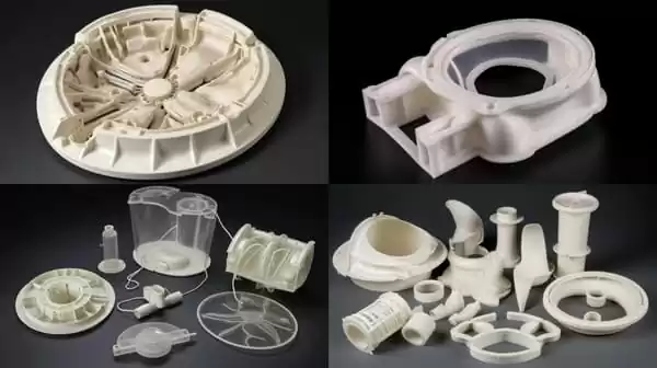
Which Approach Costs Less Over the Program Life?
Neither route wins by default. Cost follows the number of molds, the trimming operations, and the assembly labor each option creates, measured over the whole program rather than at first article.
| Factor | One piece | Multi piece |
|---|---|---|
| Tooling | One mold, one forming tool | One mold per component |
| Trimming | One trim operation, one fixture | One trim fixture per part, more complex edges |
| Assembly | None | Flanges, fasteners, seals, alignment |
| Thickness risk | Concentrated in deep draws | Spread across shallower draws |
| Typical failure modes | Corner thinning, webbing on deep male forms | Joint gaps, misaligned fastener patterns, seal leaks |
| Best fit | Large smooth shells with a manageable draw ratio | Deep, undercut, or separable geometry |
Volume changes the picture as well. At low volumes, one additional mold is a visible cost; at high volumes, assembly labor dominates, and a one piece shell that removes even two fastening operations per unit often pays back a more expensive mold quickly. Estimate cost per shipped assembly, not per formed part.
"Splitting a design into several vacuum formed parts always reduces tooling cost."False
Each additional component brings its own mold, trim fixture, and inspection plan, and the assembly stage adds fasteners and labor that did not exist before. Programs routinely find that three easy parts cost more than one well-engineered difficult part.
"A multi piece program saves money only when each component simplifies the draw and shares a coherent trim and assembly strategy."True
The saving comes from shallower draws, simpler trim lines, and easier handling, not from the split itself. If every new part needs a unique mold and a unique fixture, the split multiplies cost instead of reducing it.
Assembly labor is the cost item buyers most often underestimate. Every added joint needs fasteners, torque control, and leak or alignment checks at incoming inspection, and those activities continue for the life of the program.
ZetarVac runs a 5-axis CNC trimming centre for formed parts, and the trimmed outline follows the forming tool. For multi piece sets, this keeps the mating edges of separate components consistent across batches, which is what makes bolt-together assemblies practical without secondary machining.
How Should You Validate Each Design Before Release?
Validation should prove material properties on formed sheet rather than resin data sheets alone, and it should cover more than one forming lot. For housings and covers, that means tensile strength, heat deflection behavior, and where applicable flammability, all documented before release.
ISO 527-2 is the standard tensile test run on thermoformed sheet, so it verifies that forming has not degraded the material below the design basis. ISO 75-2 defines the heat deflection temperature of a plastic under a specified flexural load4, which sets the service-temperature margin of a formed enclosure before it starts to soften. For electrical and industrial covers, UL 945 classifies the flammability of plastic materials and is the rating many equipment enclosures must document before approval. Independent background on the process family is available from the SPE Thermoforming Division.
"A passed first article proves a vacuum formed part will stay stable in production."False
A first article reflects one sheet lot, one machine setting, and one ambient condition. Sheet gauge drift, regrind ratio, and heater aging all move the forming window, so a part that passed once can drift out of limits within weeks.
"Stability must be confirmed across sheet lots and the full forming window, with documented tests."True
Run capability checks on at least two or three sheet lots and record thickness at mapped points on the formed part. Tie acceptance criteria to measured data, such as tensile results per ISO 527-2[^iso527], so later batches are judged against evidence rather than memory.
Both approaches deserve the same discipline. A one piece shell concentrates risk in its deep-draw zones, while a multi piece set spreads it across interfaces, so map the inspection points accordingly instead of sampling only the easy flat areas.
ZetarVac supports prototyping, small batch, and large batch production, with reference monthly capacity of about 100,000 to 200,000 pieces across 45+ production lines. That range matters at validation: the same forming process that produces your samples repeats at volume, so the forming window you qualify is the window that ships.
FAQ
Can a large enclosure always be replaced by a single vacuum formed part?
No. If the geometry needs undercuts, extreme draw depth, or separated service access, a single shell either cannot form or thins below specification. Check the draw ratio and the trim envelope first, then decide whether a split genuinely adds function or only adds joints.
How deep can one piece vacuum forming go?
Common heavy gauge practice keeps the depth-to-width ratio moderate so wall distribution stays predictable, although capable tooling and the right material extend the limit. Deep draws thin corners fastest, so verify actual thickness at mapped points rather than trusting the starting sheet gauge.
Does splitting into several parts improve quality?
It improves repeatability per part, because each draw is shallower and each trim line simpler. Total assembly quality then depends on flange design and fastener consistency, which must be engineered and measured like any other tolerance chain.
Which materials suit each approach?
Both approaches draw on the same material families. ABS and PC/ABS dominate equipment housings and automotive interior parts, HDPE and PP serve industrial trays and liners, and PC suits clear guards and protective covers. Stiffer materials hold shape better on deep draws but demand more forming heat.
What is the realistic next step before committing to a design?
Map your geometry against the draw, trim, and assembly factors above, then compare how each option behaves in a forming trial. To keep researching before any supplier discussion, explore the vacuum forming process hub or see how a heavy gauge thermoforming program is structured from prototype through batch production.
-
Draw ratio: The ratio of a formed part’s depth to its narrowest plan-view width; higher ratios mean more sheet stretching and more thinning. ↩
-
Draft angle: The taper built into walls perpendicular to the sheet so the formed part releases from the mold without dragging. ↩
-
Webbing: Wrinkles or bridges of excess material that form across cavities when the sheet bridges between male mold peaks. ↩
-
HDT: Heat deflection temperature, the temperature at which a plastic deforms under a defined flexural load per ISO 75-2. ↩
-
UL 94: The flammability classification standard for plastic materials, commonly required documentation for formed equipment enclosures. ↩