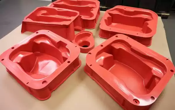
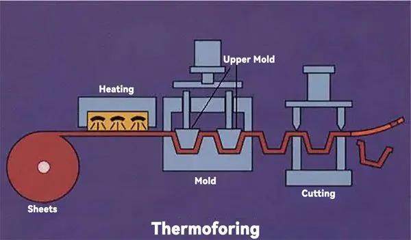
A mold material decision is made once, but it repeats itself on every part that comes off the machine. In heavy-gauge thermoforming, the tool sets the cooling rate, the surface finish, the draft geometry and, ultimately, the dimensional stability of every enclosure, tray or structural panel shipped from it. This guide walks through the mold materials used in vacuum forming, what each one costs, where each one fails, and how to match the material to the part, the polymer and the volume. For a wider view of the process family, see the overview of heavy-gauge thermoforming.
- The mold material controls cooling rate, surface texture and dimensional stability of every formed part — not just the tool price.
- Machined aluminum is the default production material for heavy-gauge work: high thermal conductivity, tight machining accuracy and full rework capability.
- Cast aluminum delivers molded-in texture at lower machining cost, but casting porosity must be controlled and sealed.
- Steel is justified for long runs, pressure forming or abrasive filled sheets where tool wear dominates the economics.
- Wood, epoxy and tooling-board molds are prototype and bridge tools, not production tooling.
- Draft angle, vacuum-hole layout and shrinkage allowance must be specified together with the material, because the three interact.
What Are the Mold Materials Used in the Thermoforming Process?
Production thermoforming molds come from five material families: machined aluminum, cast aluminum, steel, and low-cost tooling such as epoxy boards and wood-filled composites. Machined aluminum is the industry default for heavy-gauge parts because it combines fast heat removal with machining accuracy. Steel and board tooling sit at the two extremes of tool life and cost.
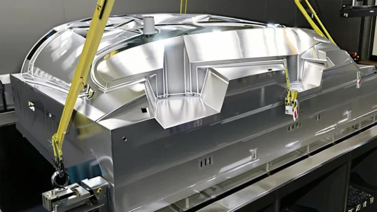
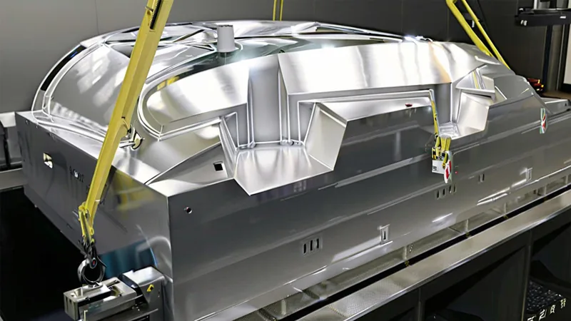
Machined aluminum. Machined aluminum, typically 5083 or 6061 plate, is CNC-cut from solid stock, which gives the most accurate forming surface and complete freedom in placing cooling channels. Conductivity in the range of roughly 130–170 W/m·K pulls heat out of the sheet quickly and evenly, which matters when a housing wall must release without distortion. Because the mold is machined, it is also reworkable: draft can be added after trial forming, vacuum holes can be relocated, and worn areas can be welded and re-cut. The trade-offs are machining cost on large surfaces and the extra effort of applying textures.
Cast aluminum. Cast aluminum is poured against a pattern, so surface textures — leather grain, sand finish, geometric patterns — are molded in at almost no incremental cost. That makes it attractive for large cosmetic panels and equipment covers. The weaknesses are porosity1 and less uniform density: voids can leak vacuum or mark the sheet, so casting quality and surface sealing are the acceptance criteria that matter. Cooling channels are harder to place than in machined stock, usually limited to cast-in pipes or back-face drilling.
Steel. Steel molds appear where tool life and wear resistance outweigh cycle time: very long runs, pressure forming at higher forming pressures, or sheets with mineral or glass fillers that abrade an aluminum surface. Conductivity around 30–50 W/m·K means slower cooling unless the cooling layout compensates, and machining cost is the highest of the metal options.
Board and composite tooling. Epoxy tooling boards and wood-filled composites machine fast and cheap, which is exactly what a prototype needs. What they cannot do is survive production: conductivity below roughly 0.5 W/m·K stretches cycles dramatically, surfaces degrade over repeated heating cycles, and accuracy drifts with moisture and temperature. Treat any board mold as a bridge tool with a bounded life.
| Mold material | Conductivity (W/m·K) | Relative tool cost | Indicative tool life | Best suited for |
|---|---|---|---|---|
| Machined aluminum (5083/6061) | 130–170 | Medium | 100,000+ cycles with maintenance | Production housings, trays, structural parts |
| Cast aluminum | 100–150 | Low to medium | 50,000–100,000 cycles | Large textured panels and covers |
| Steel (P20 or tool steel) | 30–50 | High | Very long | Long runs, pressure forming, filled sheets |
| Epoxy tooling board | 0.2–0.5 | Low | Tens to low hundreds of cycles | Prototypes and design verification |
| Wood-filled composite | 0.2–0.4 | Lowest | Tens of cycles | Early fit checks and bridge tooling |
The tool-life figures above are order-of-magnitude conventions. Actual life depends on the polymer, the sheet fillers, forming temperature and maintenance discipline, so treat them as planning inputs rather than guarantees.
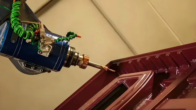
How Does Mold Material Affect Cooling and Cycle Time?
Cooling commonly takes 60–80 % of a heavy-gauge thermoforming cycle, and the mold is the heat sink that controls it. Aluminum conductivity moves heat hundreds of times faster than tooling board, which is why the material choice changes cycle time more than any other tooling decision.
In vacuum forming, the sheet is formed against the mold while hot and then cooled below its heat deflection temperature before it can be released without distortion. ISO 75-2 defines the heat deflection temperature of plastics under flexural load, which is the property that tells you how cold a part must be before demolding2. A mold that cannot pull heat out fast enough holds the part captive longer, with no quality gain, or releases it hot and accepts warp in the rack.
Each polymer also wants a different mold temperature. ABS typically forms against tools held somewhere around 60–85 °C, PC runs hotter at roughly 90–120 °C, and PP sits between; the right window depends on sheet gauge and machine, so treat these as starting ranges rather than fixed setpoints. A tool that is too cold blurs detail and can freeze the sheet before it fully conforms; one that is too hot stretches the cycle and risks sticking.
Cooling-channel design follows the material. Machined aluminum lets you drill channels exactly where heat concentrates — deep corners, thick flange lands, boss areas. Cast tools usually work with fewer, larger cast-in passages. Board tooling has none, so cooling is slow conduction plus still air.
ZetarVac runs more than 20 vacuum forming and thermoforming machines and processes sheet from 0.5 to 15 mm thick, with maximum forming length of about 2,500 mm. Tool size and cooling layout are therefore engineered to a known machine window, not to generic platens.
"Cycle time depends almost entirely on sheet heating, so the mold material barely matters."False
Heating and cooling are two halves of the same cycle, and cooling is usually the longer half. A low-conductivity mold keeps the part captive long after the sheet is formable and can easily double the cycle time of the same part.
"Mold material and cooling-channel design control most of the forming cycle."True
Correct. The cooling share of a heavy-gauge cycle commonly reaches 60–80 %, and conductivity differences between aluminum, steel and board tooling span orders of magnitude. Specify the cooling layout together with the material, not afterwards.
That is also why prototype parts formed on board tooling rarely match the cycle time of production parts formed on aluminum. Geometry differences deserve a closer look.
Which Mold Details Depend on the Material Choice?
Draft angles, vacuum-hole layout, shrinkage allowance and surface texture are all specified differently for machined, cast and board tooling. A detail that is routine on machined aluminum can be impractical in a casting and impossible on a tooling board.
Draft angles exist so the cooled part releases instead of hanging up. Male tools commonly run 1–3°, female cavities 2–5°, and deep draws or textured surfaces need more; a workable rule of thumb is to add roughly 1° of draft per 0.25 mm of texture depth3. Cast molds with molded-in grain therefore demand more draft than a polished machined mold for the same geometry.
Vacuum forming pulls the sheet down through small holes or slots, and hole size is a compromise. Too large leaves witness marks on cosmetic surfaces; too small clogs or evacuates air too slowly. Machined aluminum holds fine holes in the 0.4–0.8 mm range cleanly, some cast tools use controlled surface porosity instead of drilling, and tooling boards cannot hold fine holes at all — one reason prototype parts draw slightly differently than production parts.
Mold dimensions must also compensate polymer shrinkage. Every resin family shrinks at its own rate, and the rate shifts with grade, sheet gauge and part geometry, so the allowance is set per material during tool design rather than copied between programs. Because shrinkage differs between resins, a mold cut for ABS will not hold tolerance in PP. This is the physical reason one mold rarely serves two polymer families, and why a promise that one tool can form any material should be treated as marketing rather than engineering.
Finally, the mold itself moves with temperature. Aluminum expands at roughly 23 µm/m·K, about twice the rate of steel4; negligible on small parts, but measurable on a 2,000 mm forming surface operating hot, and worth raising with the toolmaker when formed features sit close to tolerance.
"Once the first article passes inspection, the mold is ready for volume production."False
A single good part proves the geometry, not the process. Sheet temperature, vacuum time and mold temperature all drift between shots, so only a run of consecutive parts shows whether the forming window is actually stable.
"Release a forming mold only after a short capability run, not after first article approval."True
Right. First article approval validates the tool geometry; a capability run validates the window around it. Ask for a defined number of consecutive parts with measured wall distribution and trimmed dimensions before accepting the tool.
Tool detail and tool material are decided together, but they are still only half the picture. The other half is the part itself: its polymer, its cosmetic demands and its volume.
How Do You Match Mold Material to Part, Polymer and Volume?
Start from three inputs: the polymer family, the cosmetic requirement and the expected lifetime volume. Machined aluminum is the safe default for production parts; cast aluminum wins when molded-in texture covers large areas; board tooling is justified only for prototypes and bridge quantities.
High-temperature resins and filled grades push toward harder, more thermally stable tool surfaces. Where a part is qualified against a material standard, the mold must be built and run for that exact resin: UL 94 governs the flammability of plastic materials and is required for many equipment enclosures5, so a housing formed from a flame-rated grade cannot be switched to an untested substitute without requalification. Glass- or mineral-filled sheet abrades aluminum, which is where steel inserts or hardened coatings earn their cost.
Validation closes the loop. ASTM D638 defines the standard tensile test for plastics, and it is the usual way to confirm that a new mold’s forming window leaves the sheet with the strength the design assumes6. Parts from a new tool are commonly compared against baseline data before the tool is signed off for production.
Clear parts change the calculus again. A PMMA display cover or a PC guard needs a highly polished tool, because every tool defect transfers to the part and shows under light — the same rules described in the guide to acrylic thermoforming. On textured ABS housings, by contrast, a cast mold hides gloss variation and handling marks.
Volume sets the crossover. A board mold costs a fraction of an aluminum tool but lasts tens to hundreds of cycles; a maintained aluminum mold amortizes over six figures of parts. For a neutral, process-level refresher on clamping, heating and forming mechanics, the thermoforming overview on CustomPartNet is a reasonable starting point.
ZetarVac forms PVC, ABS, HDPE, LDPE, PP, PC, PMMA, PA6/PA66, POM, TPE, TPU, TPV, PC/ABS, ASA and PP/GF. Each family brings its own shrinkage, forming temperature and release behaviour, so mold shrinkage allowances and temperature settings are held per grade, not per machine.
"Wood or epoxy tooling is always the cheapest route to a finished part."False
Board tooling is cheap per tool, not per project. When a board mold cannot hold texture, cools slowly or wears out mid-programme, replacement and revalidation costs exceed what a production mold would have cost up front.
"Low-cost tooling only pays off when part complexity and volume are both low."True
Exactly. For fit checks, trade-show samples and early design loops, board tooling is the right tool. Once the geometry is frozen and volumes are counted in thousands, machined aluminum is usually the lower total-cost option.
With the decision logic in place, the questions below cover the points buyers raise most often before committing to a tooling route.
FAQ: Mold Materials in Thermoforming
How long does an aluminum thermoforming mold last?
A maintained machined aluminum mold in heavy-gauge work is conventionally expected to run into six figures of cycles. The real variables are sheet fillers, forming temperature and maintenance discipline. Wear shows up first on high-draw radii and vacuum-hole edges, both of which are repairable by welding and re-machining.
Can one mold form different plastics?
Rarely with any precision. Shrinkage, forming temperature and release behaviour differ between families, so a mold dimensioned for ABS will not hold tolerance in PP without redesign and requalification. Sharing a mold across resins is realistic only for non-critical prototype parts.
Does mold texture transfer to every formed part?
Texture transfers most where the sheet is drawn tight against the tool and least in deep corners and draping areas. Texture depth also raises the effective draft requirement, so a texture chosen for cosmetics has to be checked against draw depth before the tool is cut.
What tolerances can a thermoformed part hold?
Forming sets the loose dimensions; trimming sets the tight ones. Because trimmed outlines are cut on 5-axis CNC equipment and follow the forming tool, cut edges hold machining-class accuracy while the formed walls carry looser, gauge-dependent tolerances.
Should I choose cast or machined aluminum?
Choose cast when molded-in texture over a large surface dominates and fine vacuum detail is limited. Choose machined when you need precise vacuum-hole placement, internal cooling channels, tight flatness or the ability to rework the tool after trials. Many programmes combine both: a machined core with cast textured inserts.
When you want to go deeper before committing to any tooling decision, explore the ZetarVac vacuum forming process guide, or see how heavy-gauge thermoforming projects are engineered from sheet selection through 5-axis trimming.
-
Porosity: Small voids within cast metal; uncontrolled porosity leaks vacuum and can mark the formed sheet surface. ↩
-
HDT: Heat deflection temperature, the temperature at which a plastic test bar deflects a specified amount under flexural load; used to judge safe demolding temperature. ↩
-
Draft angle: The taper on mold walls that allows a cooled part to release without scoring or hang-up. ↩
-
CTE: Coefficient of thermal expansion, the fractional dimensional change of a material per degree of temperature change. ↩
-
UL 94: The flammability standard for plastic materials, classifying resins by burning behaviour; many equipment enclosures require a rated grade. ↩
-
ASTM D638: The standard tensile test for plastics, used to validate sheet and formed-part mechanical properties. ↩