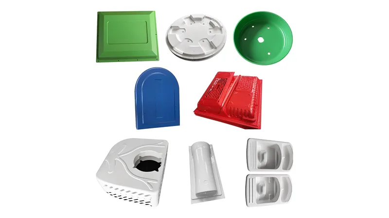
Thermoformed packaging problems rarely show up in the quotation. They show up on the line: a tray whose cavities run thin at the corners and crack under stacking load, a lid flange warped out of plane so it no longer seals, webbing stretched across cavities that stops products from seating. This article walks through the defects that matter in heavy-gauge thermoforming, traces each one to a process root cause, and gives buyers and engineers concrete rules for inspection, acceptance, and design.
- Most thermoforming packaging defects trace back to four variables: sheet temperature, vacuum application, cooling balance, and trimming.
- Thin corners, webbing, and warpage are functional defects; light surface blush is cosmetic only if the specification allows it.
- A signed-off first article proves tooling and setup, not that every later batch will hold the same tolerances.
- Wall thickness distribution must be verified on formed parts, never assumed from the sheet gauge.
- Sampling plans such as AQL turn defect acceptance into a defensible, repeatable decision.
- Draft angle, corner radius, and draw depth decisions remove most defects before the forming tool is cut.
What Counts as a Defect in Thermoformed Packaging?
A defect is any deviation from the agreed drawing or specification that affects function, fit, or appearance beyond the agreed limit. In vacuum forming that covers wall thickness below the drawing minimum, flanges warped out of sealing tolerance, webbing between cavities, blisters in the sheet, and trimming that misses the specified outline.
The split between functional and cosmetic defects has to be written down before production starts. A surface blush on a black PVC tray may be invisible in service; the same blush on a clear PC cover is an immediate reject. Buyers who accept a phrase like good surface finish without agreeing a reference sample leave the decision to whoever inspects the batch that day.
Thickness is the clearest example. Formed parts never carry the sheet gauge uniformly: stretched areas thin out while clamped areas stay near nominal. A packaging drawing should therefore state a minimum wall thickness at defined critical zones rather than a blanket value. Sheet processed in the 0.5–15 mm range behaves differently at each end of that window, so the acceptance plan must match the gauge actually being formed.
Defects also need separating from normal variation. Wall thickness in vacuum forming always varies within a band; the question is whether the minimum stays above the drawing requirement. Writing acceptance as a measurable limit at a defined location, rather than a subjective impression, is what turns quality discussions from opinions into pass or fail decisions that survive an audit.
Where Do Vacuum Forming Defects Come From?
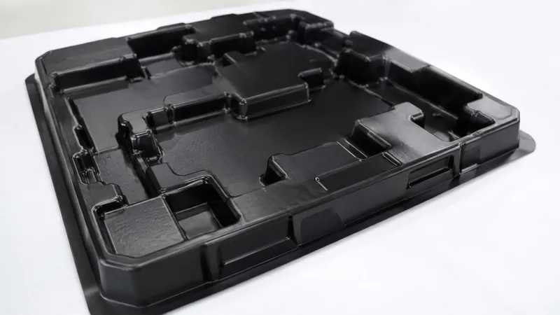
Nearly every defect traces back to four process variables: sheet temperature at the moment of forming, how vacuum is applied and vented, how heat is removed, and how the part is trimmed. Material choice and tool design decide how much margin each variable has before a thermoforming defect appears.
Heating errors come first. A sheet that reaches the forming station below its forming window stays stiff and produces thin corners and weak detail; an overheated sheet sags unpredictably and blisters, especially where hygroscopic resins have absorbed moisture. Material selection sets the risk profile: PVC and PP dominate packaging trays, ABS carries industrial housings and guards, while PC and PMMA serve clear covers where any optical defect is visible at a glance.
Vacuum application comes second. Vents that are too few or badly placed leave trapped air pockets — the classic blister over a deep male core — while a vacuum that pulls the sheet too fast can freeze it thin before it fully drapes. Forming rate, plug assist depth, and vacuum sequencing are tuned together, not independently.
Cooling and trimming close the loop. Parts released while the flange is still hot distort on the rack, and uneven tool temperature warps large panels. Trim errors — drift, burrs, missed registration — turn a geometrically sound part into an assembly failure, which is why formed parts should be finished on a 5-axis CNC trimming centre where the trimmed outline follows the forming tool.
A share of defects starts before the sheet reaches the oven. Sheet stored without wrapping picks up moisture that flashes into bubbles in hygroscopic resins, and sheets scuffed in storage show marks that forming magnifies into visible streaks. Checking incoming sheet — gauge, moisture where relevant, surface condition — costs little and removes defects that no forming parameter can fix later.

How Do the Major Defects Compare on Cause and Acceptance?
Each defect has a dominant cause, a detection method that works on the shop floor, and a tolerance decision that belongs in the specification. The table below summarizes the six defects behind most packaging quality disputes in thermoforming and vacuum forming.
| Defect | Typical root cause | Detection method | Acceptance guidance |
|---|---|---|---|
| Thin corners | Draw ratio too aggressive, sheet too cold | Ultrasonic gauge or cut section vs drawing minimum | Reject below minimum wall |
| Webbing | Sheet too hot, cavity spacing too tight | Visual check at formed flanges | Reject if it blocks seating or stacking |
| Blisters | Sheet overheated, moisture in resin | Visual, back-lighting on clear parts | Reject — structural and visible |
| Warpage | Unbalanced cooling, part demolded too hot | Flatness check on a surface plate | Reject if flange sealing is affected |
| Blush or marks | Uneven sheet heating, tool contact | Visual vs agreed reference sample | Accept only within agreed cosmetic limit |
| Trim burr or offset | Trim tool wear, part movement | Go/no-go gauge on trimmed outline | Reject — assembly fit is affected |
The table is a starting point, not a verdict. The same visual signature can have different roots — a blister can be moisture, overheating, or a blocked vent — so the cause column reflects the most common driver, and a proper root-cause review changes one variable at a time. Rejecting a batch without recording which variable drifted guarantees the dispute repeats on the next order.
Two rows deserve extra attention because buyers get them wrong repeatedly: the status of a first article and the status of webbing.
"Once a first article is approved, every production batch will match it."False
A first article proves the tool geometry and the process setup at one point in time. Sheet lots, oven condition, and cooling water temperature still drift between runs, so the outcome shifts with them unless batch sampling continues.
"First-article approval and batch inspection answer different questions."True
The approved first article validates tooling and process capability; incoming batch inspection checks that the process stayed inside its window. Buyers need both, and neither one substitutes for the other.
That distinction is also why supplier process-control data matters when comparing forming suppliers, not only unit prices.
ZetarVac processes sheet from 0.5 to 15 mm and forms parts up to about 2,500 mm long, finishing formed parts on a 5-axis CNC trimming centre whose trimmed outline follows the forming tool. For packaging buyers, this means trim-related defects such as burrs, offset outlines, and mismatched cavities are controlled by machining the trim path from the same geometry that formed the part, rather than by manual re-registration.
How Should Buyers Inspect Incoming Thermoformed Packaging?
Incoming inspection should pair a defined sampling plan with four physical checks: wall thickness at the marked critical zones, flange flatness, cavity-to-cavity consistency, and trim accuracy against a go/no-go gauge. Visual comparison against an agreed reference sample closes the loop for appearance defects.
A sampling plan built on the Acceptable Quality Limit1 gives both sides a shared statistical basis for accepting or rejecting a batch, instead of arguing over individual parts. For thickness, an ultrasonic gauge on the marked points works for routine checks, while a saw-cut section at a deep corner gives the definitive picture. Flange flatness is checked on a surface plate with feeler gauges, and trim accuracy with a hard gauge that either fits or does not.
Clear parts add one more check: a light table reveals thin zones and trapped-air blisters that are hard to see under normal lighting. It takes minutes per batch and catches the two defects most likely to reach a customer unnoticed.
For repeat programs, measurement consistency matters as much as the checks themselves. Agree in advance which instrument reads thickness, which points are measured, and who owns the reference sample. Two factories measuring the same part with different gauges will reach two different conclusions — and neither is wrong about the part, only about the method.
"Webbing between cavities is purely cosmetic and can be accepted."False
Webbing is excess material stretched across the gap between cavities, and the adjacent walls thinned as a result. It also stops nested products from seating and interferes with stacking, which makes it a functional defect rather than a surface blemish.
"Webbing severity should be judged against function, not appearance."True
A light web at a non-critical location may be acceptable by written agreement; a web that prevents product insertion or pulls wall thickness below the drawing minimum is a reject. The specification should state which case applies before the first batch ships.
At production volume, the value of batch records grows quickly, because drift shows up in sampling statistics before it reaches a customer.
ZetarVac runs more than 20 vacuum forming machines across 45+ production lines, with a reference monthly capacity of about 100,000–200,000 pieces. At that volume, defect statistics accumulate fast, so process drift surfaces in the sampling data days before it would appear as a field complaint — one more reason ongoing batch records matter more than a single approval report.
Can Design Choices Remove Defects Before the Tool Is Cut?
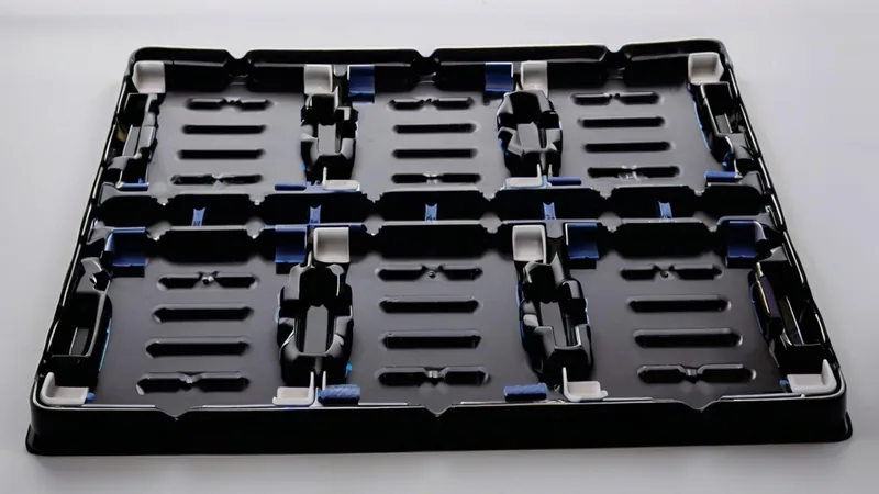
Yes. Most thermoforming defects are designed in before the mold is built: draw depth beyond the material’s proven window, corner radii too sharp for the gauge, cavity spacing that invites webbing, and flanges that cool unevenly. Fixing these at the design review is far cheaper than reworking a forming tool.
Draw depth is the first lever. For heavy-gauge vacuum forming, a depth-to-width ratio around 1:1 or shallower is a safe starting point for simple cavities; deeper draws need plug assist or billow pre-stretch to keep corners inside the material’s forming window, and the exact limit depends on material and machine. Corner radii of at least one sheet thickness — preferably 1.5 to 2 times — spread the stretch instead of concentrating it at a sharp radius. Draft angles of 1–3° on male forms and 2–5° on female forms let the part release without pulling the flange out of tolerance, and cavity gaps narrower than the sheet’s webbing tendency produce webs on almost every cycle.
If packaging will see hot-fill, pasteurization, or closed containers in transport heat, the material’s heat deflection temperature2 — not just room-temperature strength data — decides whether a flat flange is still flat when it reaches the customer. For a material-by-material breakdown of sheet options, the ZetarVac thermoformed packaging guide covers selection for trays, enclosures, and protective packaging.
For the production-side view of how oven profiles, vacuum sequencing, and trim paths are set and verified run by run, see the thermoforming packaging production process walkthrough.
"Thicker sheet always fixes thin corners in formed packaging."False
Raising the gauge adds thickness everywhere, including where material already pools, and it worsens corner webbing and cycle time. Corner thinning is governed by draw geometry, forming temperature, and plug assist, not by gauge alone.
"Draw ratio and corner radius are the first levers against thin corners."True
Conservative draw depth and generous corner radii spread the stretch across more surface, which raises minimum wall without adding weight everywhere. Gauge is then chosen for stiffness and load, with thickness verified on the formed part.
None of these rules add cost on paper; every one of them is expensive to retrofit into steel or a running production schedule.
FAQ
What is the most common defect in vacuum formed packaging?
Thin corners and webbing lead the list, because both come from the same stretch behavior at deep or closely spaced features. They are also the defects most often missed by visual-only inspection, which is why thickness checks at defined points belong in every packaging acceptance plan.
Can wall thickness be uniform across a formed part?
No. Forming is a stretching process, so thickness always varies — deep corners thin out while clamped areas stay near nominal. The realistic target is a minimum wall thickness at specified critical zones, verified on formed parts rather than assumed from sheet gauge.
Which defects only show up after the parts ship?
Thermal warpage and creep under stacking load. A flange that is flat on the inspection bench can distort in a hot container or under sustained load, so heat performance should be judged from material data, not from the as-received part alone.
How do material certificates connect to defect acceptance?
ASTM D638 defines the standard tensile test used to verify that thermoformed sheet actually delivers the strength a packaging load calculation assumes, so tensile reports should back any load-bearing claim.3 Where packaging protects electrical equipment, UL 94 governs the flammability rating of the plastic, and the rating of the finished part depends on the sheet grade actually used.4
When should a buyer ask for a process review instead of returning a batch?
When the same defect repeats across consecutive batches with a stable tool. That pattern points to a process window issue — heating, vacuum, or cooling — rather than an inspection miss, and a joint review of the forming window usually resolves it faster than repeated rejections.
If you are building defect criteria into a new packaging specification, explore ZetarVac’s vacuum forming capabilities to see how sheet selection, forming windows, and trimming are matched to the part, or learn how a China vacuum forming manufacturer supports packaging programs from prototype through series production.
-
AQL: Acceptable Quality Limit, the worst tolerable quality level used in sampling inspection to decide whether a batch is accepted or rejected. ↩
-
HDT: Heat Deflection Temperature, the temperature at which a plastic test bar deflects a defined amount under a defined flexural load. ↩
-
ASTM D638: The standard test method for tensile properties of plastics, widely used to validate thermoformed sheet and formed parts. ↩
-
UL 94: The standard for flammability of plastic materials, with ratings such as V-0 and HB commonly specified for enclosures and covers. ↩