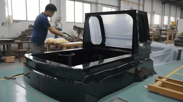
Draw depth decides whether a part can be vacuum formed as one piece or has to be split, redrawn, or redesigned. Buyers often ask for a single number — the maximum depth a thermoforming machine can pull. The honest answer is more useful than any fixed figure. Depth is only the numerator; what actually governs the limit is how the sheet stretches as it is drawn, and that is captured by draw ratio, corner geometry, sheet gauge, and the process window the molder can hold. This article explains how to judge whether your part sits inside that window before tooling is cut.
- There is no universal maximum draw depth. Feasibility is judged by draw ratio — formed depth divided by the narrowest mold width the sheet must cover at that depth.
- In heavy-gauge thermoforming, straight vacuum forming is comfortable at draw ratios up to roughly 0.7–1.0; beyond about 1.5 the process demands plug assist, prestretch, or a part redesign.
- Deep draws thin the sheet unevenly. Corners and vertical walls lose the most thickness, so wall thinning — not machine stroke — usually fails the part first.
- Sheet gauge cuts both ways: heavier sheet resists thinning but sags more before forming, cycles slower, and needs longer cooling.
- Absolute depth is capped by the machine envelope. With a maximum forming length of about 2,500 mm and sheet from 0.5–15 mm, check envelope first, then draw ratio.
What Is the Maximum Draw Depth for Vacuum Forming?
There is no fixed maximum draw depth for vacuum forming. The practical limit is a draw ratio — formed depth divided by the narrowest inside width the sheet must cover — of roughly 0.7–1.0 for straight vacuum forming and up to about 1.5 with plug assist or prestretch. Absolute depth is then capped by the machine envelope: forming length reaches about 2,500 mm on sheet from 0.5–15 mm at ZetarVac.
Depth and draw ratio get confused because a 600 mm deep pan over a 1,200 mm wide mold is an easy form, while the same 600 mm depth over a 400 mm wide base sits near the edge of what vacuum alone can pull. Depth only means something relative to the footprint it is drawn from. That is why a serious supplier asks for the widest cross-section before quoting a deep draw, and why draw depth guidelines are expressed as ratios rather than millimeters.
Why Draw Ratio — Not Depth Alone — Sets the Limit
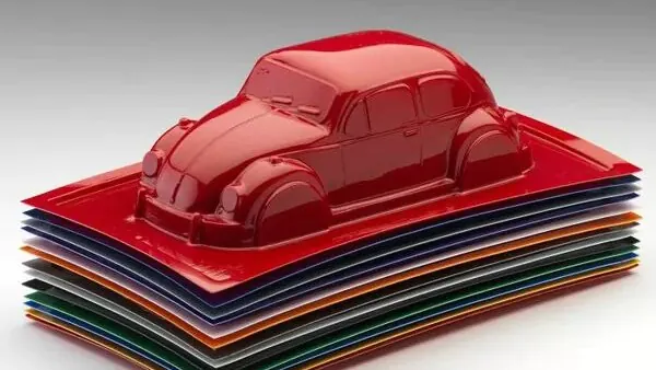
Draw ratio is the single most predictive number in heavy-gauge thermoforming.1 It compares how far the sheet must travel downward against the narrowest width it must span. As the ratio rises, three things happen at once: the sheet stretches further in the corners, the walls contact the mold later, and the vacuum has to pull a longer, cooler, sagging path of material. Each effect pushes wall thickness toward its minimum sooner.
Draw ratio is calculated from the tightest cross-section, not the average one. A tray may be shallow across most of its footprint yet have a deep, narrow channel for a connector or hinge boss; that channel sets the draw ratio for the whole part. Review every cross-section before signing off a depth figure.
The table below is how thermoforming shops typically grade feasibility. Treat the bands as engineering starting points, not specifications — material, sheet gauge, and tooling shift each band by a meaningful margin.
| Draw ratio (depth ÷ width) | Feasibility with vacuum alone | What it takes |
|---|---|---|
| Below 0.7 | Comfortable | Straight vacuum forming with standard radii |
| 0.7 – 1.0 | Workable | Generous draft angles, filleted corners, wall-thinning checks |
| 1.0 – 1.5 | Demanding | Plug assist or prestretch, heavier gauge, careful vacuum routing |
| Above 1.5 | Rarely practical | Redesign, part splitting, or pressure forming |
One caution on the top band: pressure forming solves the detail problem, not the thinning problem. It presses material against the mold surface but adds no sheet area, so corner thinning still applies.

How Deep Can You Form Before Wall Thickness Fails?
The wall fails when local thickness drops below your minimum specification, and in deep draws that happens at the inside corners and the lowest vertical walls first. A workable screening rule: assume corners in a near-1:1 draw lose 30–50% of starting gauge, then verify against a measured wall distribution.
In an ideal draw the sheet would stretch uniformly and thickness would fall with the square root of the area increase. Real forming is never ideal. Material that touches the mold first freezes early and stays thick; the last regions to contact — inside corners and deep vertical walls — keep stretching and carry the thinning. That is why the limiting check on a deep part is minimum wall at the corners, not whether the machine can physically reach the depth.
Sheet selection should be validated on measured properties rather than datasheet values alone. ISO 527-2, the standard tensile test for plastics, defines how the tensile properties of thermoformed sheet are measured, so the elongation and modulus figures you design against are reproducible across sheet lots.2 For parts that see heat in service, heat deflection temperature matters as much as depth, because a deep panel that softens at operating temperature fails no matter how well it formed.3
Material choice moves the practical limit as much as geometry does. ABS and PC/ABS offer a wide forming window and stretch predictably, which is why they dominate deep housings, cases, and guards. PC reaches deep draws while retaining stiffness but demands tighter temperature control. HDPE and PP stretch readily yet recover on release, so they need careful mold temperature management. TPU and other soft grades tolerate extreme stretch but serve flexible protection parts rather than structural panels.
Verification is straightforward and worth doing before release. Section a formed prototype through the deepest corner and measure thickness at fixed intervals up the wall; the thinnest reading sets your true minimum wall. Repeat across a second sheet lot if the volume justifies it. For enclosures and covers, pair the wall survey with a stiffness check, since flexural performance of the trimmed panel is what the assembly actually feels.
"Thicker sheet automatically lets you form deeper."False
Corner thinning is driven by stretch distribution, not starting gauge. A heavier sheet sags more before forming, cools more slowly, and can still violate the minimum wall check — now with longer cycles and a heavier part.
"Draw ratio and corner geometry decide the limit, not gauge alone."True
The reliable way out of a marginal draw is geometric: widen the footprint, increase radii, add draft, or split the part. Gauge changes shift where thinning starts; they rarely remove it.
A practical review sequence for a deep part: compute the draw ratio at the tightest cross-section, estimate corner thinning against your minimum wall, confirm the material’s heat capability, then check the machine envelope. Skipping that order is how deep parts get redesigned after tooling is already cut.
ZetarVac processes sheet from 0.5–15 mm and trims every formed part on a 5-axis CNC centre, so a deep-drawn part can be judged on its measured wall distribution and trimmed to the forming tool’s own geometry instead of a separate fixture.
When Does a Deep Draw Need Design Changes?
Draw ratios above 1.0, inside radii smaller than the sheet thickness, flat vertical walls, and features packed into corners are the classic signals. Each one concentrates stretch exactly where the sheet is already thinnest, and no process aid fully compensates for all of them at once.
Vertical walls with small radii are the worst offenders because they generate webbing — folds of excess material bridging between features — and act as thickness killers. A common shop rule: inside radii at least equal to sheet thickness, preferably larger on deep walls, with draft angles of 2–3° minimum and more on deep draws so the part releases without distortion.
Process aids come next. A plug assist4 pushes the hot sheet partway into the mold before full vacuum is applied, so more material reaches the bottom corners before they freeze. Prestretch works from the other direction by inflating the sheet uniformly first. Both extend the reachable draw ratio toward 1.5, but both add tooling cost and setup variables, so they are justified by the geometry rather than added by default.
"A good first article proves the deep draw is production-stable."False
A first article comes from a tuned mold, one selected sheet lot, and often manual cycle adjustments. Deep draws sit near the edge of the process window, so only a documented window across sheet lots and shifts shows the draw will hold in volume.
"Deep-draw stability is demonstrated with a documented process window."True
Ask for the forming parameters — sheet temperature, vacuum time, plug depth, cooling time — that produced the approved part, and how much variation around them was tested. A supplier who can answer has genuinely characterized the draw.
What Machine Envelope Defines the Realistic Maximum?
Absolute depth is bounded by the machine’s clamp area, platen stroke, and vacuum box depth, and trim capability then decides how accurately the formed flange can be removed. ZetarVac forms sheet from 0.5–15 mm with a maximum forming length of about 2,500 mm.
Before draw ratio is even discussed, absolute size has to fit the machine. The forming area sets the largest sheet you can clamp, and the stroke and vacuum box set how far it can travel downward. ZetarVac runs 20+ vacuum forming machines with a reference monthly capacity of about 100,000–200,000 pieces, so envelope checks on length, width, and depth come before any tooling conversation. Depth also interacts with overall size: a wide, deep part consumes clamp area and stroke simultaneously, which is why the maximum formable part size deserves its own review for large panels.
The second envelope question is trimming. A deep part leaves the mold with extra flange material that has to be removed accurately, often near cut-outs and mounting features at the bottom of the draw. ZetarVac trims formed parts on a 5-axis CNC centre, which matters here because the trim path can follow the formed geometry at any angle — critical for housings, covers, and trays with angled walls.
Prototyping, small batch, and large batch production are all supported across 45+ production lines in total, so a deep-draw design can be proven on a small run and scaled up without requalifying a fundamentally different process.
FAQ
How do I calculate the draw ratio of my part?
Measure the formed depth from the clamped flange plane to the deepest point, then divide by the narrowest inside width the sheet must span at the deepest cross-section. For rectangular parts use the short side; for irregular parts check every cross-section and use the worst case.
Can vacuum forming reach a 2:1 draw ratio?
Rarely with vacuum alone, and only with plug assist, heavy prestretch, and forgiving geometry. Most thermoforming shops treat anything above 1.5 as a redesign conversation rather than a process problem, because corner thinning at that ratio usually violates minimum wall requirements.
Does thicker sheet help deep draws?
It improves puncture resistance and stiffens the flange, but it does not remove corner thinning. Heavier gauge also sags more, needs more heat, and cycles longer, so the thinning problem often just moves into a slower, more expensive process.
What wall thickness should I expect on a deep draw?
Plan for the formed wall to be thinner than the starting sheet at corners and deep walls, with the distribution depending on material and geometry. Agree a minimum wall at the tightest corner as the acceptance criterion rather than a uniform nominal value. For gauge selection, see the maximum forming thickness limits.
Where should I start with a deep-drawn design?
Start by computing the draw ratio at the worst cross-section, then explore the vacuum forming guide to see how materials, tooling, and forming methods map to deep geometries. To understand how a heavy-gauge molder approaches deep parts, review the vacuum forming capabilities page.
-
Draw ratio: The ratio of formed part depth to the narrowest mold width the sheet spans at that depth; the standard feasibility metric for deep-drawn thermoformed parts. ↩
-
ISO 527-2: The part of ISO 527 that specifies test conditions for determining the tensile properties of plastics, including rigid sheet specimens. ↩
-
HDT: Heat deflection temperature, the temperature at which a plastic specimen deflects a defined amount under a specified flexural load. ↩
-
Plug assist: A mechanical plug that pushes heated sheet partway into the mold before vacuum is applied, moving material toward deep corners. ↩