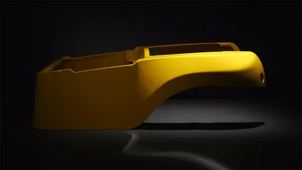
Thermoforming turns a flat plastic sheet into a finished three-dimensional part by heating it until it softens, pulling it against a single-sided mold with vacuum, and cooling it into shape. In heavy-gauge work — sheet from 0.5 mm up to 15 mm — the process wins on large part size, low tooling cost, and fast development cycles rather than on raw cycle time. This guide covers the process window, material selection, dimensional capability, relevant standards, and tooling decisions that decide whether a formed part meets spec and stays in budget.
- Heavy-gauge thermoforming processes plastic sheet from 0.5 mm to 15 mm thick, which makes it practical for machine covers, equipment housings, trays, and structural panels that are too large for most other molding routes.
- Material choice drives the design: ABS balances cost and formability, PC adds impact and heat resistance, PMMA gives optical clarity, and blends such as PC/ABS cover automotive interiors and housings.
- Formed surfaces move; trimmed features are precise. Expect formed dimensions to follow material shrinkage and draw geometry, while 5-axis CNC trimming holds tight cut-line tolerances.
- Draw ratio, draft angle, and corner radius determine whether a design forms cleanly or produces webbing, thin corners, and warped flanges.
- Validation should use recognized tests — tensile per ISO 527-2, flexural stiffness, heat deflection, flammability, and ingress protection — matched to the part’s duty.
How Does Heavy-Gauge Thermoforming Work?
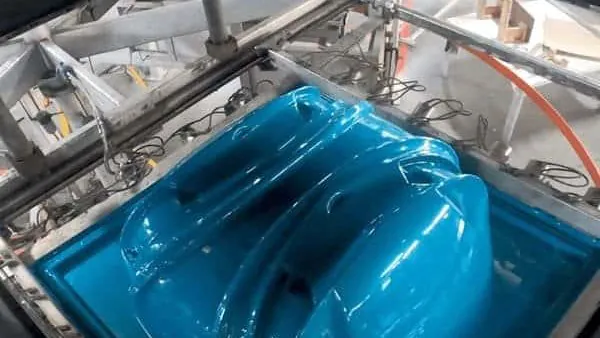
Heavy-gauge thermoforming heats a thick plastic sheet until it becomes rubbery, draws it against a single-sided mold with vacuum, and cools it into a rigid part. Because only one mold surface shapes the part, wall thickness comes from the starting sheet and thins wherever the material stretches.
The sequence is simple to describe and unforgiving to execute. A clamped sheet passes under zoned radiant heaters, and the target is a sheet-temperature window: ABS is commonly formed with sheet surface temperatures in the range of roughly 130–180 °C depending on grade and gauge, while PC and PMMA need higher heat and a longer soak. Under-heating leaves spring-back and blurry detail; over-heating causes sag, glossy marks, and degradation. On long parts, heater zones are trimmed individually so the deepest-draw regions run hottest.
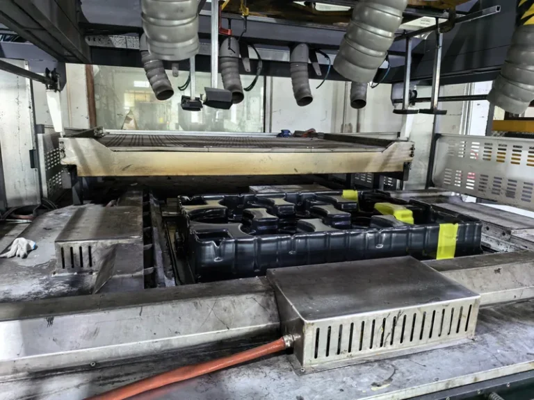
At forming temperature the sheet is indexed over the tool and vacuum is drawn through ports — usually holes below about 1 mm in diameter — pulling the sheet onto the mold surface. Production machines commonly operate with vacuum levels in the −0.6 to −0.9 bar range, depending on pump capacity, seal quality, and clamp-frame leak tightness. The practical design variable is the draw ratio1 that measures how far the sheet must stretch; the higher it is, the more the sheet thins at corners and the more likely webs form between features. Plug assists and pre-stretch help push material into deep corners before vacuum locks it against the tool.
Cooling, not forming, dominates the cycle. Thick sections may need several minutes of contact cooling before the part is stiff enough to release without warping, and uneven cooling is the main root cause of bow and twist on large panels. Draft angles of about 1–3 degrees on male tools, generous corner radii, and ribbed rather than flat large surfaces all reduce risk.
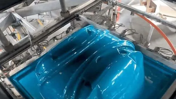
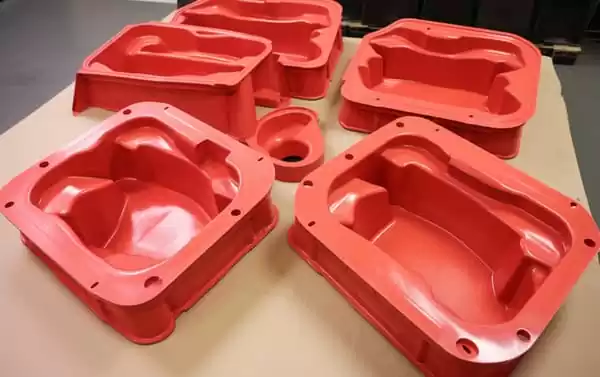
ZetarVac runs more than 20 vacuum forming and thermoforming machines, processes sheet from 0.5 mm to 15 mm, and forms parts up to about 2,500 mm in length. For buyers, that means large single-piece covers — machine guards, equipment housings, vehicle panels — can be formed in one piece instead of assembled from several smaller shells.
Which Materials Suit Vacuum Forming Best?
ABS is the default for housings, cases, and guards; HDPE and PP dominate industrial trays, liners, and boxes; PC and PMMA serve where impact or clarity matters; and TPE, TPU, and TPV cover soft liners, seals, and flexible protection parts. The right choice balances formability, service temperature, cost, and any regulatory duty.
ABS earns its position through a wide forming window, stable shrinkage, and good cosmetic finish, and it is used for automotive interior parts, equipment housings, cases, and guards. Its heat deflection temperature2 — typically around 85–100 °C at 1.8 MPa for common grades — sets the practical service ceiling for unloaded housings. PC raises impact strength and heat resistance for clear guards and protection covers, while PC/ABS blends are the standard answer for automotive interiors where both toughness and processability are needed.
For enclosures that house electrical equipment, the formed sheet frequently has to carry a flammability rating under UL 943, which constrains material selection before any other criterion is discussed. When optical clarity is the requirement, PMMA covers and display parts are specified by transmittance: ISO 13468 defines the method for measuring total luminous transmittance of transparent plastics, and it is the accepted way to state and accept clear formed covers. HDPE and PP trade stiffness for chemical resistance and low cost, which suits industrial trays and equipment liners but demands tighter warpage control.
| Material | Typical formed applications | Strengths | Watch-outs |
|---|---|---|---|
| ABS | Housings, cases, guards, auto interiors | Wide forming window, good finish | Limited UV stability |
| PC/ABS | Automotive interiors, equipment housings | Impact plus processability | Moderate heat ceiling |
| PC | Clear guards, protection covers | High impact, heat tolerance | Higher forming temperature, drying sensitivity |
| PMMA | Clear covers, luminaires, displays | Optical clarity, weatherability | Narrower forming window, more brittle |
| HDPE | Industrial trays, liners, boxes | Chemical resistance, low cost | Higher shrinkage, warpage |
| PP | Trays, boxes, auto interiors | Chemical resistance, low cost | Sag control, lower stiffness |
| ASA | Outdoor housings, exterior parts | UV and weather resistance | Higher material cost |
| TPE/TPU/TPV | Soft liners, seals, flexible sleeves | Elastomeric fit and protection | Narrower process window on sheet |
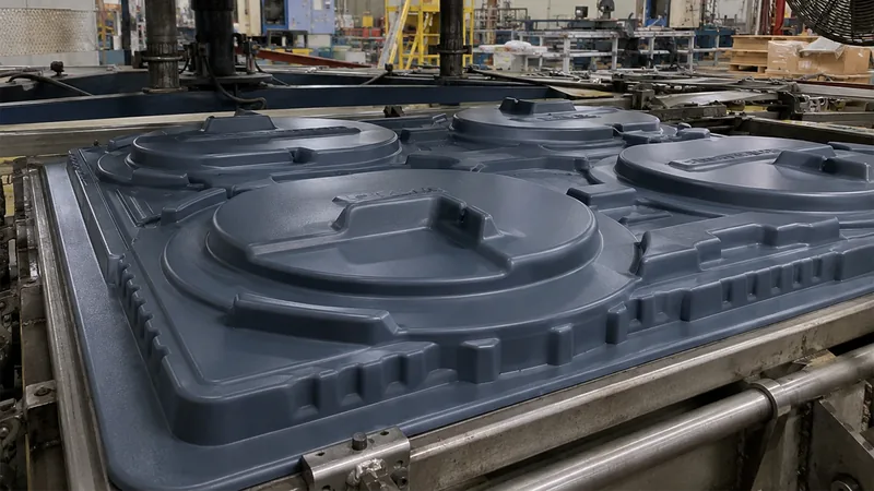
ZetarVac’s material library covers PVC, ABS, HDPE, LDPE, PP, PC, PMMA, PA6/PA66, POM, TPE, TPU, TPV, PC/ABS, ASA, and PP/GF, mapped to applications from agricultural trays to medical housings. Real production examples include multi-cavity ABS seedling trays, large PC medical equipment housings with custom cut-outs and mounting holes, and high-clarity PMMA retail display covers.
What Wall Thicknesses and Part Sizes Are Practical?
Processed sheet on heavy-gauge lines runs from 0.5 mm to 15 mm, with forming lengths up to about 2,500 mm. That spans thin packaging parts through machine-size covers and structural panels; the practical limit is usually draw ratio and cooling time, not the machine envelope.
Start gauge and final gauge are different numbers. On deep draws, corner thinning of roughly 30–50% relative to the starting sheet is a normal engineering expectation, so critical minimum walls should be called out on the drawing rather than assuming the sheet gauge carries through. Where stiffness is the goal, formed ribs, domes, and return flanges deliver far more rigidity per gram than blanket thickness increases, and they cost almost nothing extra because the mold reproduces them every cycle.
"Doubling sheet thickness is the cheapest way to double panel stiffness."False
Flexural stiffness scales with roughly the cube of thickness, so doubling the sheet overshoots the target by a wide margin while adding material cost and extending cooling time. Ribs, domes, and flanges reach the same stiffness target with far less weight.
"Formed geometry usually beats added thickness for stiffening a panel."True
A formed rib or dome increases the section’s moment of inertia at negligible marginal cost, because the mold produces it on every cycle. Thickness increases add material, extend cooling, and push the part further from uniform shrinkage behaviour.
ZetarVac supports prototyping, small batch, and large batch production on the same process platform, with reference monthly capacity in the range of 100,000–200,000 pieces. For a buyer, the useful takeaway is that a design proven in prototype tooling can move to series volumes without changing process families. For a deeper comparison of wall classes, see the thick-gauge thermoforming guide.
What Tolerances Can a Thermoformed Part Hold?
Formed surfaces typically hold tolerances on the order of ±1% of the characteristic dimension, with thick sheet and deep draws at the looser end; CNC-trimmed outlines hold much tighter limits, commonly within a few tenths of a millimetre on mid-size parts and looser as part size grows. The discipline that makes thermoforming workable is declaring which features are formed and which are trimmed, tolerancing each accordingly, and validating with a first article4 before approving series supply.
Formed dimensions inherit mold shrinkage — roughly 0.4–0.7% for ABS and noticeably more for polyolefins — plus warpage from uneven cooling, so datum schemes should anchor on trimmed features and tool-controlled surfaces. For covers that must seal or protect electronics, ingress protection is specified through the IP code5 defined in IEC 60529, and the formed geometry — gasket grooves, overlapping flanges, mounting bosses — is what turns a shaped shell into an enclosure that can meet a stated rating. Sheet properties themselves are validated with standard tensile testing: ISO 527-2 specifies the tensile test method used to characterize plastic sheet, and it is the standard basis for comparing material lots and verifying formed-part performance claims.
"Passing first article inspection proves the process is stable for series production."False
A first article verifies tool condition and setup once, on one sheet from one lot. Heater drift, sheet-lot variation, and ambient changes move formed dimensions across a run, so stability needs periodic checks on agreed control features.
"Run-to-run stability needs periodic dimensional checks, not just a one-off approval."True
Sampling key dimensions at agreed intervals catches heater and material-lot drift before nonconforming parts ship. Control features should be defined on the drawing — trim outlines, mounting-hole patterns, and critical minimum walls.
How Do Tooling and Trimming Decisions Drive Cost?
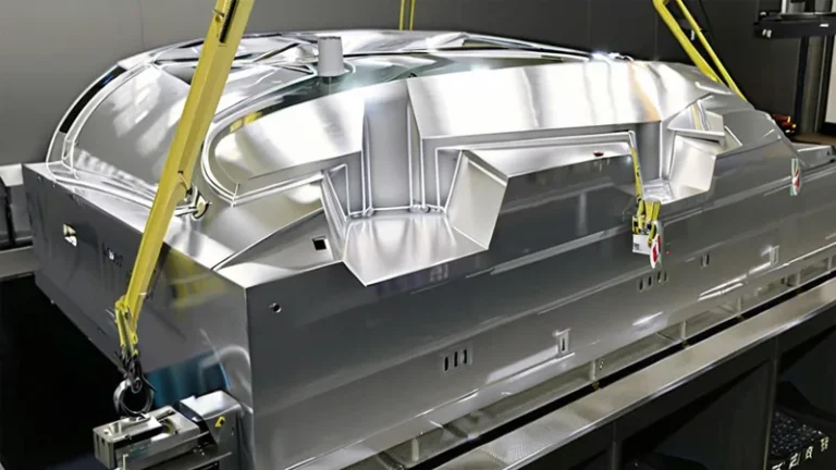
Thermoforming uses single-sided tooling, which is why prototype molds can be machined quickly and production tools are typically machined aluminum. Male tools give more uniform walls on deep draws; female tools protect the cosmetic outer surface and keep the part’s outer dimension predictable. Vacuum-hole layout, plug-assist design, and cooling-channel placement are the tool details that most influence wall distribution and cycle time, and they are worth arguing about before the first chip is cut.
Trimming is the second half of the cost equation. Formed parts are finished on a 5-axis CNC trimming centre, and the trimmed outline follows the forming tool, which keeps cut lines consistent from part to part and holds hole patterns and flange edges to drawing. Good fixtures locate off formed datums rather than relying on manual marking, and that choice shows up directly in assembly fit on the customer’s line.
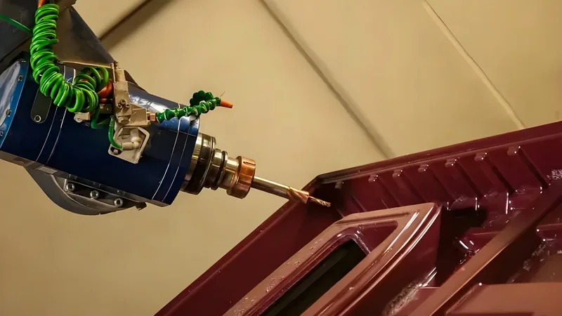
ZetarVac operates 45+ production lines across the plant, combining forming machines with a 5-axis CNC trimming centre for formed parts. Integrating forming and trimming in-house keeps trim datums consistent with the mold, which shortens the loop when a first article needs adjustment.
Tool maintenance is routine but non-optional: vacuum ports clog, textures wear, and cooling channels foul, all of which show up first as cosmetic defects and wall-thickness drift. The SPE Thermoforming Division publishes process fundamentals and troubleshooting references that align well with how experienced shops commission and maintain tools.
FAQ
Is vacuum forming the same as thermoforming?
Vacuum forming is a thermoforming variant that uses vacuum alone to press the heated sheet against the mold. Thermoforming as a family also includes pressure forming, which adds air pressure on the sheet’s outer side for crisper detail and sharper texture transfer on cosmetic surfaces.
How thick can thermoformed sheet be?
Heavy-gauge equipment commonly processes sheet from 0.5 mm up to about 15 mm. ZetarVac processes 0.5–15 mm sheet with a maximum forming length of about 2,500 mm, which covers packaging parts through machine-size housings and panels.
Is thermoforming cost-effective for low volumes?
Yes, because single-sided tooling costs a fraction of matched-metal alternatives and lead times are short. Prototyping, small batch, and large batch production are all supported, so volumes can scale without changing process.
Which standards matter for formed equipment enclosures?
UL 94 flammability for the sheet material, IEC 60529 for ingress protection ratings, and NEMA 250 for enclosure types are the usual references. Material lots are typically verified with tensile testing to ISO 527-2.
How do I keep wall thickness consistent on deep parts?
Keep the draw ratio reasonable, use plug assists or pre-stretch for deep cavities, and ask for heater-zone tuning on long parts. Most importantly, specify critical minimum walls on the drawing so thinning is measured against a defined target.
Where should I go next on thermoforming design?
Explore the ZetarVac vacuum forming guide for process selection and design details, or see how a China-based vacuum forming manufacturer handles heavy-gauge projects from tooling to trimmed parts. Both walk through the decisions that shape cost and quality before you commit to a design.
-
Draw ratio: The ratio of formed part surface area to the original clamped sheet area; higher draw ratios stretch the sheet thinner, driving corner thinning and setting the practical depth limit. ↩
-
Heat deflection temperature (HDT): The temperature at which a standard bar deflects a specified amount under a defined flexural load, measured per ASTM D648 or ISO 75-2; a practical indicator of a formed part’s service temperature ceiling. ↩
-
UL 94: A flammability standard that classifies the burning behaviour of plastic materials, for example V-0 or HB; many formed equipment enclosures require the sheet material to carry a specified rating. ↩
-
First article inspection: Full dimensional and functional verification of one initial production part against the drawing; it confirms tool and setup but does not by itself prove run-to-run stability. ↩
-
IP code: The ingress protection rating defined in IEC 60529, for example IP54, which classifies how well an enclosure excludes dust and water. ↩