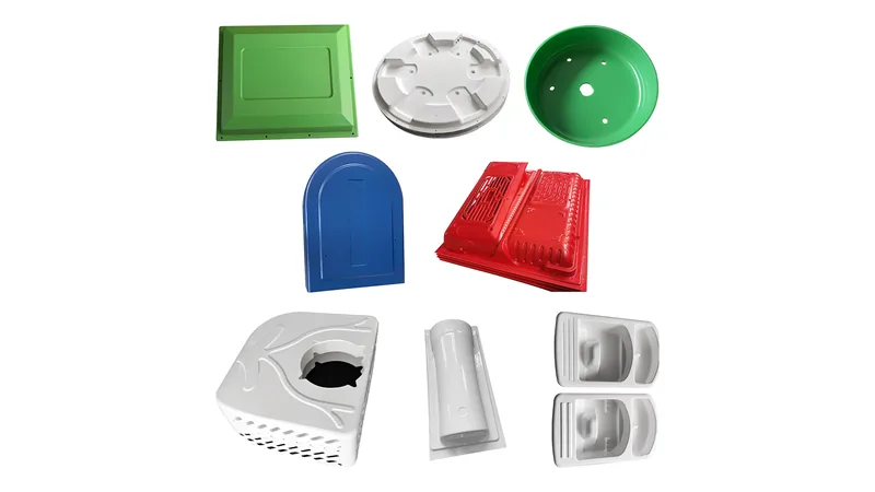
Every heavy-gauge thermoforming project starts with one number: the sheet gauge you order. That value decides forming depth, corner quality, cycle time, and how much wall variation the part will show after trimming. Buyers often assume the finished wall simply inherits the starting sheet, and that assumption causes most thickness disputes at first-article inspection. This guide gives working ranges for the thinnest and thickest sheets that vacuum forming handles, explains where the thickness actually goes during forming, and shows how to write a thickness callout a forming shop can quote without guessing.
- Industrial thermoforming covers roughly 0.5–15 mm of sheet; heavy-gauge vacuum forming works the upper part of that window, and ZetarVac processes the full 0.5–15 mm range with forming lengths up to about 2,500 mm.
- Formed wall thickness never equals sheet gauge: corners and deep-draw walls can finish 30–50% thinner while flanges stay close to nominal.
- The upper limit is set by heating, sag and cooling, not by tool size; above roughly 10–12 mm, heat-soak time and edge-to-center temperature gradients dominate.
- The lower limit is set by webbing, sag and dimensional drift; structural formed parts rarely go below about 1 mm of starting sheet.
- Specify minimum wall at named features instead of nominal gauge alone, and validate strength on formed walls with tensile testing per ISO 527-2.
- Material and gauge must be chosen together; ABS, HDPE, PC, PP and PMMA each carry a different practical window.
What Are the Maximum and Minimum Thicknesses of Thermoformed Sheets?
In industrial practice, thermoforming handles sheet from roughly 0.5 mm at the thin end to about 15 mm at the thick end. Heavy-gauge vacuum forming works the upper part of that window, typically from about 1.5 mm upward, while the lower end belongs to thin-gauge packaging work. There is no single universal limit: the achievable range depends on material, heater power and tool design, so treat these figures as process windows rather than hard walls.
The starting gauge is the ceiling for every wall on the part, because forming only redistributes material — it never adds any. A 6 mm sheet can deliver a 6 mm flat flange, but a corner drawn 300 mm deep may finish closer to 3 mm. At the other extreme, the thinnest usable gauge is bounded by handling: below about 0.5 mm, sheet sags unpredictably in the oven and clamping becomes unreliable.
The useful question for a buyer is therefore not how thick thermoforming can go in general, but how thick the thinnest feature of your specific part can go at its draw depth with its material. Those are different numbers, and only the second one matters for strength, stiffness and compliance.
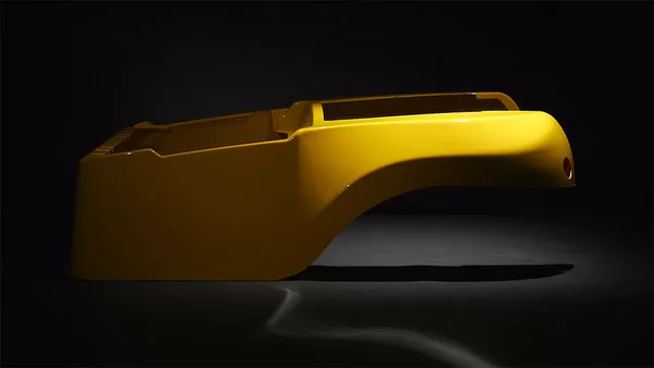
ZetarVac processes thermoforming sheet from 0.5 to 15 mm with a maximum forming length of about 2,500 mm, running on more than 20 vacuum forming machines across a plant of 45+ production lines. For a buyer, that means the full gauge window is served on one floor, so a product family spanning thin liners and thick structural covers does not have to be split across suppliers.
What Happens to Wall Thickness During Vacuum Forming?
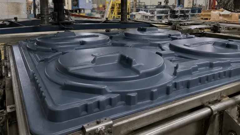
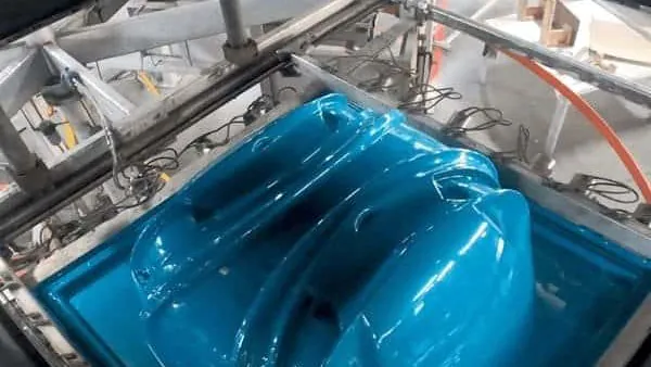
Vacuum forming stretches a heated sheet over a tool, so material thins wherever it elongates. On deep draws, corners and side walls commonly finish 30–50% thinner than the starting sheet, while clamped flange areas stay close to nominal gauge.
The driver is draw ratio1 — the ratio of formed surface area to the original flat sheet area. Higher draw ratios mean more stretch, and thinning concentrates where the sheet meets the tool last: inside radii, deep pocket corners, and the transition from side wall to base. Male tools thin the sheet as it drapes over the form; female tools thin it where it bottoms out. Plug-assist pre-stretch redistributes some of that loss by pushing thicker material into corners before vacuum pulls the sheet home.
Webbing is the thick-sheet version of the same physics2. When a hot, heavy sheet bridges between two tall features, it folds on itself instead of stretching, leaving wrinkles that no amount of vacuum will remove. Both defects trace back to the same decision — asking a given gauge to cover more geometry than it can handle at that temperature.
"A 6 mm starting sheet gives a 6 mm wall on every feature of the formed part."False
Forming only stretches material, never adds it. Corners and deep-draw walls routinely finish 30–50% below nominal gauge, so strength calculated from the full 6 mm does not exist where the part actually carries load.
"Formed wall thickness must be verified at corners and deep-draw walls, not assumed from the sheet gauge."True
Section a first article or use ultrasonic gauging at the thinnest predicted features, then write minimum-wall callouts at those exact locations. That is the only way a drawing survives contact with the forming tool.
Because the wall that ships is thinner than the sheet that started, strength validation has to run on formed parts, not on raw sheet certificates. ISO 527-2 defines the standard tensile test method for plastics3, and on heavy-gauge programs it is the accepted method for confirming that a stretched, re-cooled wall still meets the strength the design assumed. For broader background on forming practice, the SPE Thermoforming Division publishes open technical resources for thermoformers.
How Thick Can Heavy-Gauge Thermoforming Actually Go?
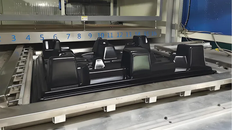
Most heavy-gauge vacuum forming tops out around 12–15 mm of sheet, depending on material and machine heating. Above roughly 10 mm, the bottleneck is no longer the tool — it is getting heat evenly through the sheet without the center sagging before forming even begins.
The physics is unforgiving: heat-soak time grows roughly with the square of thickness, so a 12 mm sheet needs several times the oven residence of a 3 mm one, and the oven must deliver that time without overheating the surface. ISO 306 defines the Vicat softening temperature4, the point at which a plastic softens under a specified load — a practical proxy for when an over-heated sheet starts to sag toward the heaters. Edge-to-center temperature gradients can easily reach tens of degrees across a wide, thick sheet, which is why heater zoning matters more as gauge rises.
Thicker sheet also pays a tax after forming. Cooling time stretches, shrinkage and locked-in residual stress grow, and fine surface detail stops reproducing because a 12 mm sheet cannot drape into sharp texture the way a 2 mm one can. Push past the practical ceiling and you are buying longer cycles and more warpage risk, not more part.
That said, the thick end is where heavy gauge earns its name: machine bases, large enclosures, tanks and column covers all live there. Gauge is also a compliance parameter in this band — UL 94 classifies the flammability of plastic materials5, and many formed equipment housings must meet a defined UL 94 rating in the exact grade and gauge that ships, because flame ratings do not transfer across thicknesses.
| Material | Practical sheet window | Typical heavy-gauge uses | Watch-outs at the limits |
|---|---|---|---|
| ABS | 1.5–9 mm | Equipment housings, guards, automotive interiors | Corner thinning on deep draws |
| HDPE | 2–15 mm | Industrial trays, equipment liners, storage boxes | Shrinkage on thick flat panels |
| PC | 1.5–9 mm | Clear guards, protection covers | Drying before forming; notch sensitivity |
| PP | 0.5–6 mm | Trays, packaging, equipment liners | Sag control; low stiffness when hot |
| PMMA | 2–10 mm | Clear covers, luminaires, display parts | Brittle trim edges; moisture pickup |
| PVC | 0.5–6 mm | Trays, packaging, industrial liners | Narrow thermal forming window |
The plant’s material library spans the whole window: ABS for housings and guards, PC and PMMA for clear covers, HDPE and PP for trays and liners, ASA for outdoor equipment, and glass-filled PP/GF for structural parts. Choosing gauge and grade together, rather than fixing one and hoping the other follows, is what keeps a program from re-qualification later.
How Thin Is Too Thin for a Structural Formed Part?
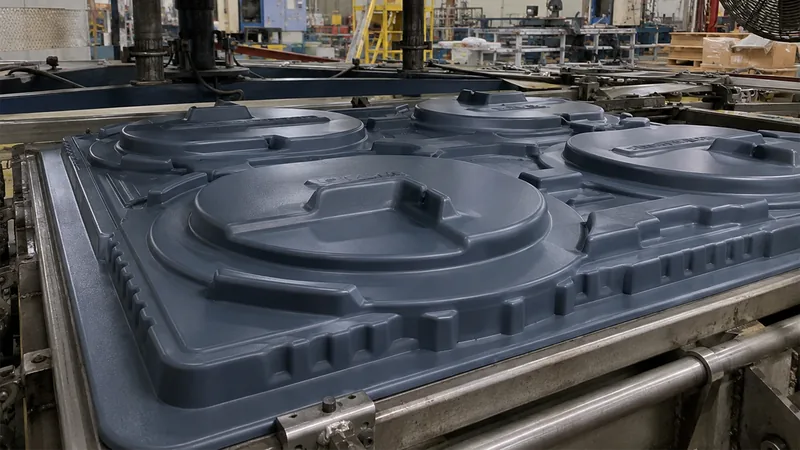
Structural thermoformed parts rarely go below about 1 mm of starting sheet. Below that line, oven sag, webbing between features and post-forming dimensional drift all grow quickly, and the part loses the stiffness that justified forming it in the first place.
Work below 1 mm down to 0.5 mm is real, but it belongs to a different operating regime: thin-wall packaging, liners and trays where containment, not rigidity, is the job. LDPE thin-wall packaging parts and PVC or PP trays sit there comfortably. If your part list includes both thin liners and thick covers, treat them as two gauge programs sharing one supplier rather than one specification stretched across both.
For enclosures and structural trays, the everyday working band is roughly 1.5–3 mm of ABS or HDPE: enough stiffness for flat panels, still formable with moderate cycle times. When a design needs more rigidity than the gauge can deliver, buy stiffness with geometry — ribs, flanges, returns and domes — before buying more millimetres. ASTM D790 defines the standard flexural test for plastics6, and it is commonly run on formed panels and enclosures to confirm that the rib-and-gauge combination behaves as the design assumed. For PP specifically, see our guide to PP thermoformed sheets for how grade choice moves the usable window.
How Do You Specify Sheet Thickness on a Thermoforming Drawing?
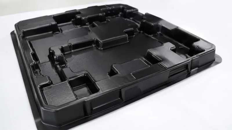
Put three things on the drawing: nominal sheet gauge with the material grade, a minimum-wall requirement at named features, and the trim datum. Nominal gauge alone tells the molder what to buy but tells the inspector nothing about what the part must survive.
Good thickness callouts follow a few habits. State minimum wall where it matters — a corner radius, a mounting boss, a bolt-hole flange — not as a blanket number. Agree the measurement method up front: sectioned first article or ultrasonic gauging, and at which features. Keep tolerances honest: the forming process sets the wall and the trimmed outline follows the forming tool, so the dimensional band should reflect the process, not machined-part expectations. And tie the gauge to the grade plus any flame rating, because a UL 94 rating quoted in the wrong thickness is not a rating.
Formed parts at ZetarVac are trimmed on a 5-axis CNC centre, so the cut outline follows the forming tool rather than a separate fixture. For thickness control that matters twice: the trim line lands on a wall that has already thinned, and the same forming-tool datum can be referenced in both the minimum-wall callout and the trim inspection.
A structured first-article inspection catches thinning before it becomes a production habit — our guide to first-article inspection for heavy-gauge thermoformed parts walks through that process step by step. Because the trim line lands where the wall has already thinned, trim datums and minimum-wall callouts belong on the same drawing; the write-up on CNC trimming of thermoformed parts covers how that outline is cut and verified.
"Nominal sheet thickness is enough information for a molder to quote and build a thermoformed part."False
Nominal gauge says what to buy, not what the part must survive. Without minimum-wall requirements at named features and an agreed measurement method, acceptance collapses into opinion at first-article review.
"A thickness callout needs nominal gauge, material grade, and minimum wall at named features."True
That combination lets the molder predict thinning, pick sheet sensibly, and accept the part against numbers instead of opinions. It also gives both sides a shared baseline when a sheet-lot change shifts gauge slightly.
"If the first article passes, sheet-gauge variation cannot affect later production batches."False
Sheet gauge drifts between lots, and oven performance drifts with it. A process qualified on one lot can thin corners differently on the next, so thickness verification belongs at defined intervals, not only at launch.
"Wall thickness should be re-verified periodically during production, especially after a sheet-lot change."True
A light ultrasonic check at the two or three thinnest predicted features is cheap insurance against silent drift. Tie the check frequency to sheet-lot changes and the thickness loop stays closed for the life of the program.

FAQ
What is the thickest sheet that can be vacuum formed?
Industrial heavy-gauge lines commonly process up to about 15 mm, and ZetarVac works across the full 0.5–15 mm window with forming lengths up to about 2,500 mm. For a specific part, the practical ceiling depends on material and draw depth, so the geometry should be reviewed before the gauge is fixed.
Does the formed wall match the sheet thickness I order?
No. Corners and deep-draw walls thin by roughly 30–50% at high draw ratios, while flange areas stay close to nominal. Verify thickness at the thinnest predicted features instead of assuming the sheet gauge carries through the part.
How is wall thickness checked on a formed part?
Two methods dominate: sectioning a first article and measuring the cut faces, or ultrasonic gauging on live parts. Both should target inside corners and deep side walls, where thinning concentrates.
Which materials suit the thick end of the range?
ABS, HDPE and glass-filled PP/GF hold up well at heavy gauge for structural housings, trays and bases. PC suits thick clear guards, and ASA carries outdoor enclosures. Enclosures with a flame requirement add a UL 94 rating in the shipping grade and gauge.
Can thermoforming go below 0.5 mm?
Thin-gauge packaging work goes below that, but it is a roll-fed, fast-cycling, non-structural regime. For structural heavy-gauge parts, treat roughly 1 mm of starting sheet as the practical floor and add stiffness with geometry instead of gauge.
Where can I read more about the process?
To see how these thickness limits play out across housings, trays and covers, explore the ZetarVac vacuum forming capability page, or review our heavy-gauge thermoforming manufacturing overview to understand how sheet selection, forming and trimming fit together on one production floor.
-
Draw ratio: the ratio of formed surface area to the original flat sheet area; higher draw ratios mean more stretching and more corner thinning. ↩
-
Webbing: wrinkles formed when a hot sheet bridges and folds between mold features instead of stretching; a common failure mode on thick sheet with deep geometry. ↩
-
ISO 527-2: the standard tensile test method for plastics, used to validate sheet and formed walls against design strength after forming. ↩
-
ISO 306: the standard defining the Vicat softening temperature, the point at which a plastic begins to soften under load — a practical indicator of when a heated sheet will sag. ↩
-
UL 94: the flammability classification standard for plastic materials; many formed equipment enclosures must meet a defined rating in the exact grade and gauge that ships. ↩
-
ASTM D790: the standard flexural test for plastics, used to rate the stiffness of formed panels and enclosures. ↩